Circular-type mixing device suitable for paint production

A kind of mixing equipment and circulating technology, which is applied in the direction of mixers, mixers with rotating stirring devices, fluid mixers, etc., can solve the problems of inability to filter paint, uneven mixing quality, and low work efficiency, and achieve improved mixing Quality, improvement of mixing efficiency and mixing quality, effect of improving product quality

Inactive Publication Date: 2018-12-11
WUHU SANSHAN LONGCHENG NEW MATERIALS
View PDF5 Cites 2 Cited by
  • Summary
  • Abstract
  • Description
  • Claims
  • Application Information

AI Technical Summary

Problems solved by technology

[0003] The purpose of the present invention is to solve the problems existing in the existing paint mixing equipment that the paint cannot be circulated and mixed, the mixing quality is not uniform, the work efficiency is not high, and the paint cannot be filtered, and to provide a device with a reasonable structure design and a paint that can be recycled many times. Mixing, good mixing quality, high work efficiency, and the ability to filter the paint is a circulating mixing equipment suitable for paint production

Method used


Image

  • Circular-type mixing device suitable for paint production
  • Circular-type mixing device suitable for paint production

Examples


Embodiment 1

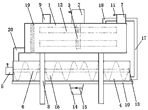
[0016] as attached figure 1 As shown, a circulating mixing equipment suitable for coating production includes mixing chamber one 1, motor one 2, transmission shaft one 3, mixing chamber two 4, motor two 5, transmission shaft two 6 and infusion pump 7, its characteristics That is, the mixing chamber-1 is arranged on the support 8, the feeding pipe 9 is arranged on the mixing chamber-1, and the backing plate 10 is arranged between the support 8 and the support 8, and the described motor-2 is set On the mixing chamber-1, a power cord 11 is provided on the motor-2, the transmission shaft-3 is arranged in the mixing chamber-1, the transmission shaft-3 is connected with the motor-2, and the transmission shaft-3 is connected to the motor-2, and the transmission shaft-3 is connected to the motor-2. 3 is provided with a stirring plate 12, the mixing chamber 2 4 is arranged on the backing plate 10, a bearing 13 is arranged on the inner wall of the mixing chamber 2 4, and a discharge bin...

Embodiment 2

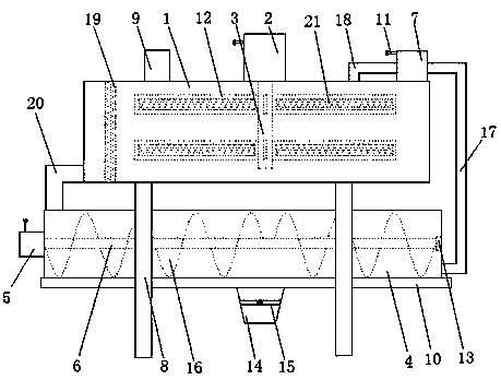
[0022] as attached figure 2 As shown, a circulating mixing equipment suitable for coating production includes mixing chamber one 1, motor one 2, transmission shaft one 3, mixing chamber two 4, motor two 5, transmission shaft two 6 and infusion pump 7, its characteristics That is, the mixing chamber-1 is arranged on the support 8, the feeding pipe 9 is arranged on the mixing chamber-1, and the backing plate 10 is arranged between the support 8 and the support 8, and the described motor-2 is set On the mixing chamber-1, a power cord 11 is provided on the motor-2, the transmission shaft-3 is arranged in the mixing chamber-1, the transmission shaft-3 is connected with the motor-2, and the transmission shaft-3 is connected to the motor-2, and the transmission shaft-3 is connected to the motor-2. 3 is provided with a stirring plate 12, the mixing chamber 2 4 is arranged on the backing plate 10, a bearing 13 is arranged on the inner wall of the mixing chamber 2 4, and a discharge bi...


PUM


Abstract

The invention discloses a circular-type mixing device suitable for paint production. The circular-type mixing device comprises a first mixing chamber, a first motor, a first transmission shaft, a second mixing chamber, a second motor, a second transmission shaft and an infusion pump. The first mixing chamber is installed on a bracket. The first motor is installed on the first mixing chamber. The first transmission shaft is installed in the first mixing chamber. The second mixing chamber is installed on a base plate. The second motor is installed on the outer wall of the second mixing chamber.One end of the second transmission shaft is installed in a bearing. The circular-type mixing device is capable of enabling the infusion pump to be connected with the second mixing chamber and the first mixing chamber through a liquid inlet pipe and an infusion pipe, enabling paint in the second mixing chamber to enter the infusion pump through the liquid inlet pipe, and entering the first mixing chamber through the infusion pipe, enabling the paint to be circularly flowed in the first mixing chamber, the second mixing chamber and the infusion pump, realizing circular stirring to the paint, andimproving mixing efficiency of the paint.

Description

technical field [0001] The invention relates to the technical field of paint processing, in particular to a circulating mixing device suitable for paint production. Background technique [0002] In the process of paint processing, it is necessary to mix different paint raw materials according to the ratio to improve the quality and performance of the paint, and the uniformity of paint mixing and stirring directly affects the quality of the paint. For example, the patent application number 201510776077.2 discloses a paint mixer. It solves the problems of high labor intensity and low work efficiency, but it has the problems that the paint cannot be mixed circularly, the mixing quality is uneven, the work efficiency is not high, and the paint cannot be filtered. Contents of the invention [0003] The purpose of the present invention is to solve the problems existing in the existing paint mixing equipment that the paint cannot be circulated and mixed, the mixing quality is not...

Claims


Application Information

Patent Timeline
IPC IPC(8): B01F5/10B01F7/08B01F7/18B01F13/10B01F15/00
CPCB01F25/52B01F27/726B01F27/90B01F33/821B01F35/187B01F2101/30
Inventor 杨荣军赵传东杨荣兵
Owner WUHU SANSHAN LONGCHENG NEW MATERIALS
Why Eureka
Try Eureka