High-efficiency pesticide mixer

A mixer and pesticide technology, applied in the field of agriculture, can solve the problems of high labor intensity of operators, poor mixing quality of pesticides, waste of liquid medicine for operators, etc., so as to improve mixing quality, improve mixing efficiency and mixing quality, and improve mixing. The effect of uniformity

Inactive Publication Date: 2018-12-07
安徽乐农环保科技有限公司
View PDF4 Cites 1 Cited by
  • Summary
  • Abstract
  • Description
  • Claims
  • Application Information

AI Technical Summary

Problems solved by technology

[0003] The purpose of the present invention is to overcome the problems existing in the existing pesticide mixers that the pesticides cannot be fully mixed, the quality of pesticide mixing is not high, and the labor intensity of the operators is high, and to provide a machine with reasonable structure design, high work efficiency, and good mixing quality uniformity. High-efficiency pesticide mixer with less labor intensity for operators and less liquid waste

Method used


Image

  • High-efficiency pesticide mixer
  • High-efficiency pesticide mixer
  • High-efficiency pesticide mixer

Examples


Embodiment 1

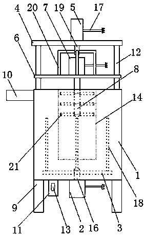
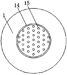
[0017] as attached figure 1 and 2 As shown, a high-efficiency pesticide mixer includes a mixing barrel 1, a motor one 2, a connecting plate 3, a top plate 4, a cylinder 5, an adjustment plate 6, a motor two 7 and a rotating shaft 8, and is characterized in that: the mixing barrel 1 is set on the bracket 9, and the mixing barrel 1 is provided with a feed pipe 10, a discharge pipe 11, and a column 12, and a transition barrel 14 is arranged on the top of the mixing barrel 1, and the motor one 2 is arranged on the mixing barrel 1 bottom, and a power cord 17 and a transmission shaft 16 are arranged on the motor one 2, and the connecting plate 3 is arranged on the transmission shaft 16, and a stirring rod one 18 is arranged on the connecting plate 3, and the top plate 4 Set on the column 12, the cylinder 5 is set on the top plate 4, and the cylinder 5 is provided with a power cord 17, a piston rod 19, the adjustment plate 6 is arranged on the column 12, and the adjustment plate 6 i...

Embodiment 2

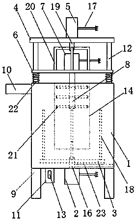
[0023] as attached image 3 As shown, a high-efficiency pesticide mixer includes a mixing barrel 1, a motor one 2, a connecting plate 3, a top plate 4, a cylinder 5, an adjustment plate 6, a motor two 7 and a rotating shaft 8, and is characterized in that: the mixing barrel 1 is set on the bracket 9, and the mixing barrel 1 is provided with a feed pipe 10, a discharge pipe 11, and a column 12, and a transition barrel 14 is arranged on the top of the mixing barrel 1, and the motor one 2 is arranged on the mixing barrel 1 bottom, and a power cord 17 and a transmission shaft 16 are arranged on the motor one 2, and the connecting plate 3 is arranged on the transmission shaft 16, and a stirring rod one 18 is arranged on the connecting plate 3, and the top plate 4 Set on the column 12, the cylinder 5 is set on the top plate 4, and the cylinder 5 is provided with a power cord 17, a piston rod 19, the adjustment plate 6 is arranged on the column 12, and the adjustment plate 6 is passe...


PUM


Abstract

The invention provides a high-efficiency pesticide mixer. The mixer comprises a mixing barrel, a motor 1, a connecting plate, a top plate, a cylinder, an adjusting plate, a motor 2 and a rotating shaft, and the mixer is characterized in that the mixing barrel is disposed on a bracket, the motor 1 is disposed at the bottom of the mixing barrel, the connecting plate is disposed on a transmission shaft, a stirring rod 1 is disposed on the connecting plate, the top plate is disposed at vertical columns, the cylinder is disposed on the top plate, the adjusting plate is disposed at the vertical columns, the motor 2 is disposed on the adjusting plate, one end of the rotating shaft is connected to the motor 2, and the other end of the rotating shaft is disposed in a transition barrel. According tothe invention, the motor 1 and the motor 2 are arranged to make reverse rotation, and further the stirring rod 1 and a stirring rod 2 are driven to rotate in reverse directions, so that a buffer barrel can separate a pesticide in the mixing barrel into two parts for reverse rotation, the pesticide is thoroughly stirred fully, and the mixing efficiency of the pesticide is improved.

Description

technical field [0001] The invention relates to the field of agricultural technology, in particular to a high-efficiency pesticide mixer. Background technique [0002] At different stages of crop planting, different agricultural methods need to be sprayed on the crops to improve the yield of the crops or the ability to resist diseases and insect pests. The mixing quality of pesticides directly affects the quality of the liquid medicine. Most of the existing pesticides are mixed manually. Low work efficiency, high labor intensity, and low mixing quality still exist. For example, the patent application number 201710595517.3 discloses an agricultural liquid medicine mixing device that is easy to disassemble and clean. The problem that the liquid has settled to the bottom, but it has the problems that the pesticide cannot be fully stirred, the quality of pesticide mixing is not high, and the labor intensity of the operator is high. Contents of the invention [0003] The purpo...

Claims


Application Information

Patent Timeline
IPC IPC(8): B01F7/00B01F7/16B01F15/00B01F13/10B01F15/02
CPCB01F27/074B01F27/116B01F33/85B01F35/12B01F35/7547B01F2101/22
Inventor 傅剑锋王强明
Owner 安徽乐农环保科技有限公司
Why Eureka
Try Eureka