Stirring device for asphalt mixture

The technology of asphalt mixture and mixing device is applied in the field of asphalt mixture, which can solve the problems of unreasonable addition method of aggregate, asphalt and mineral powder, poor mixing quality of asphalt mixture, unreasonable movement state of coarse and fine aggregate, etc. Achieve the effect of improving production efficiency and road performance, increasing effective spraying area, improving mixing quality and mixing efficiency

Inactive Publication Date: 2020-02-04
JILIN UNIV
View PDF6 Cites 3 Cited by
  • Summary
  • Abstract
  • Description
  • Claims
  • Application Information

AI Technical Summary

Problems solved by technology

However, in traditional asphalt mixing, the three cannot be efficiently mixed to form an optimal stable structure.
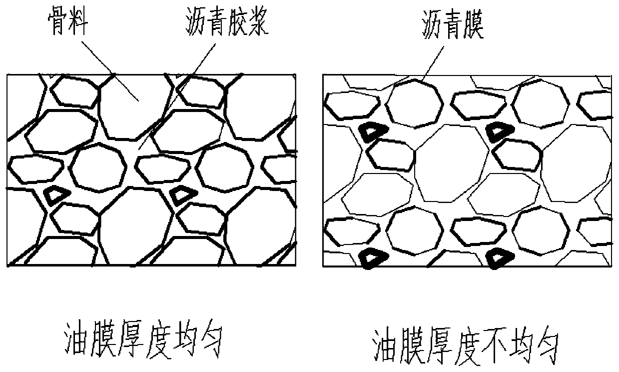
There are three main defects: one is that the asphalt is poured into the mineral material in a relatively concentrated manner, resulting in uneven thickness of the asphalt layer on the surface of the mineral material, and even the phenomenon of "blocking"
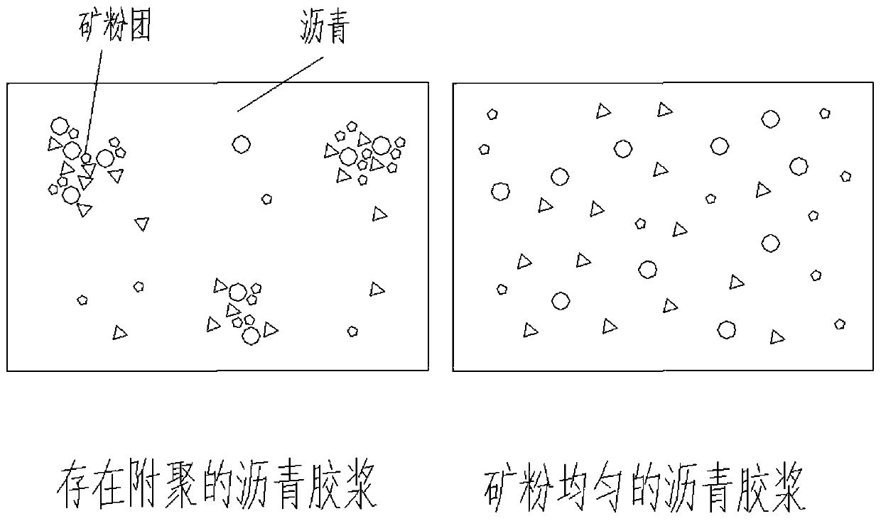
The second is that the addition of mineral powder to the asphalt mineral mixture is uneven, and the phenomenon of "agglomeration" of mineral powder and asphalt is easy to occur. The third is that the movement state of coarse and fine aggregate is unreasonable, resulting in the phenomenon of "segregation" of the mixture
[0003] Existing engineering applications show that the performance of pavement declines, and even early large-area damage occurs, the direct reason is that the mixing quality of asphalt mixture is not high
The root cause is that the asphalt mixture raw materials are not free to move freely in the mixing chamber, and the addition of aggregate, asphalt and mineral powder is unreasonable, resulting in a loss of control over the production quality of the product

Method used


Image

  • Stirring device for asphalt mixture
  • Stirring device for asphalt mixture
  • Stirring device for asphalt mixture

Examples


Embodiment Construction

[0048] The present invention will be described in detail below in conjunction with the accompanying drawings.

[0049] Such as Figure 6 As shown, a kind of asphalt mixing device proposed by the present invention, it comprises from top to bottom successively: feed inlet 8, air blast type slag powder spraying device 1; 23; semi-ellipsoidal primary mixing bin 3; half bin type rotating stirring device 4; primary mixing bin burner; circular frustum-shaped slidable vertical support device 5; primary discharge port 45; secondary mixing bin 6; double horizontal shafts Paddle stirring device 7, secondary stirring bin burner; discharge port 9.

[0050] The detailed size, structure and function of the device are introduced as follows:

[0051] The feed inlet 8 is located at the upper left of the primary mixing chamber 3, and is in the shape of a trapezoidal groove, the inclined surface is 40°-50° from the horizontal direction, and the junction with the primary mixing chamber 3 is arc-...


PUM


Abstract

The invention relates to a stirring device for an asphalt mixture. The stirring device for the asphalt mixture comprises a primary stirring bin and a secondary stirring bin, wherein a blast type mineral powder spraying device and an air pressure type asphalt spraying device are arranged in the primary stirring bin, and a half bin type rotating stirring device is positioned at the lower part of theprimary stirring bin; a double horizontal shaft paddle stirring device is arranged in the secondary stirring bin, and a discharge port is formed on the lower end of the secondary stirring bin; the primary stirring bin is supported above the secondary stirring bin by a frustum-shaped sliding vertical support device. For the engineering problems in the prior art, the stirring device for the asphaltmixture aims at realizing efficient mixing of aggregate, asphalt and mineral powder. Through changing the mixing form of the asphalt mixture, the free movement state and effective spraying area of the mineral powder are increased, the spraying uniformity of the asphalt and the mineral powder is increased, the full range coverage of a discrete mineral powder region is realized, and the mixing quality and the mixing efficiency of the asphalt mixture are improved.

Description

technical field [0001] The invention relates to the technical field of asphalt mixture, in particular to an asphalt mixture stirring device. Background technique [0002] Asphalt mixture is an important material for road construction. It is composed of three basic materials—aggregate—asphalt—and mineral powder. The three are effectively mixed to form a road structure layer with excellent performance. However, in traditional asphalt mixture mixing, the three components cannot be efficiently mixed to form an optimal stable structure. There are three main defects: one is that the asphalt is poured into the mineral material in a concentrated manner, resulting in uneven thickness of the asphalt layer on the surface of the mineral material, and even the phenomenon of "blocking". The second is that the mineral powder is not uniformly added to the asphalt mineral mixture, and the mineral powder and asphalt are prone to "agglomeration". The above three aspects are the root causes o...

Claims


Application Information

Patent Timeline
IPC IPC(8): E01C19/10
CPCE01C19/10E01C19/104E01C19/1063
Inventor 邹琳琳徐衍青
Owner JILIN UNIV
Why Eureka
Try Eureka