
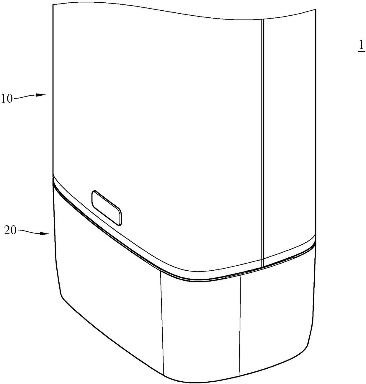
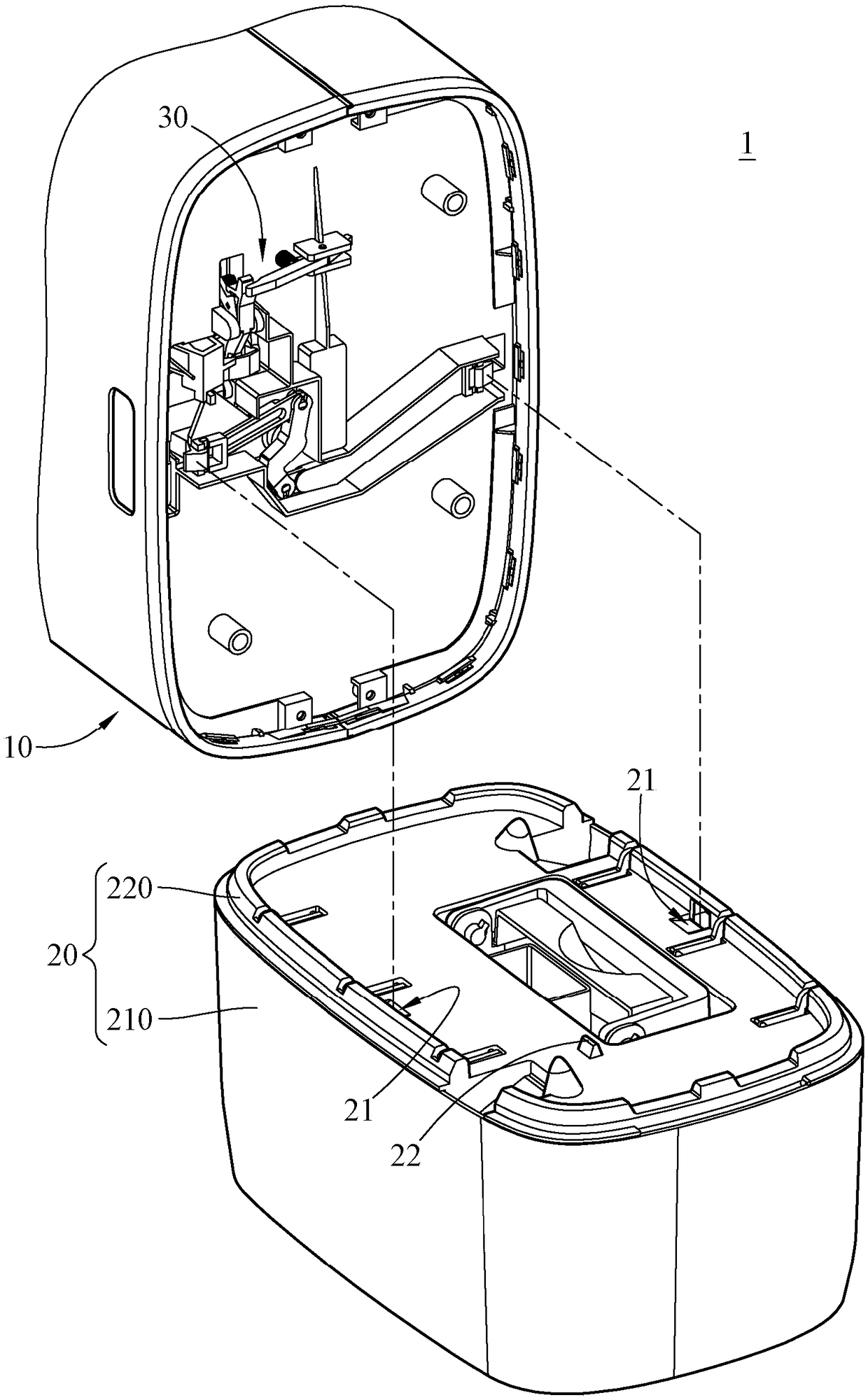
Dehumidifier and buckle mechanism

A dehumidifier and buckle technology, which is applied to a buckle mechanism including a pressing piece, and a dehumidifier field including a buckle mechanism, can solve the problem that the water tank cannot be combined to move as one, the operation of the combination mechanism of the body and the water tank is inconvenient, and the dehumidifier cannot be operated. Match with different volume water tanks, etc.

Inactive Publication Date: 2018-12-11
NORM PACIFIC AUTOMATION
View PDF10 Cites 2 Cited by
  • Summary
  • Abstract
  • Description
  • Claims
  • Application Information

AI Technical Summary

Problems solved by technology

[0005] In view of this, the present invention provides a dehumidifier and a buckle mechanism to solve the problems that the traditional dehumidifier cannot be matched with water tanks of different volumes, or cannot be combined with water tanks to move as one, or the combination mechanism of the body and the water tank is inconvenient to operate.

Method used


Image

  • Dehumidifier and buckle mechanism
  • Dehumidifier and buckle mechanism
  • Dehumidifier and buckle mechanism

Examples


Embodiment Construction

[0071] The detailed features and advantages of the present invention are described in detail in the following embodiments. The content is sufficient to enable any person skilled in the art to understand the technical content of the present invention and implement it accordingly, and is based on the content disclosed in this specification, the scope of protection of the claims and With the accompanying drawings, any person skilled in the art can easily understand the related objects and advantages of the present invention. The following examples further illustrate the viewpoint of the present invention in detail, but do not limit the scope of the present invention by any viewpoint.

[0072] In addition, the embodiments of the present invention will be disclosed in the following drawings. For clear description, many practical details will be described in the following description. However, it should be understood that these practical details are not intended to limit the present in...


PUM


Abstract

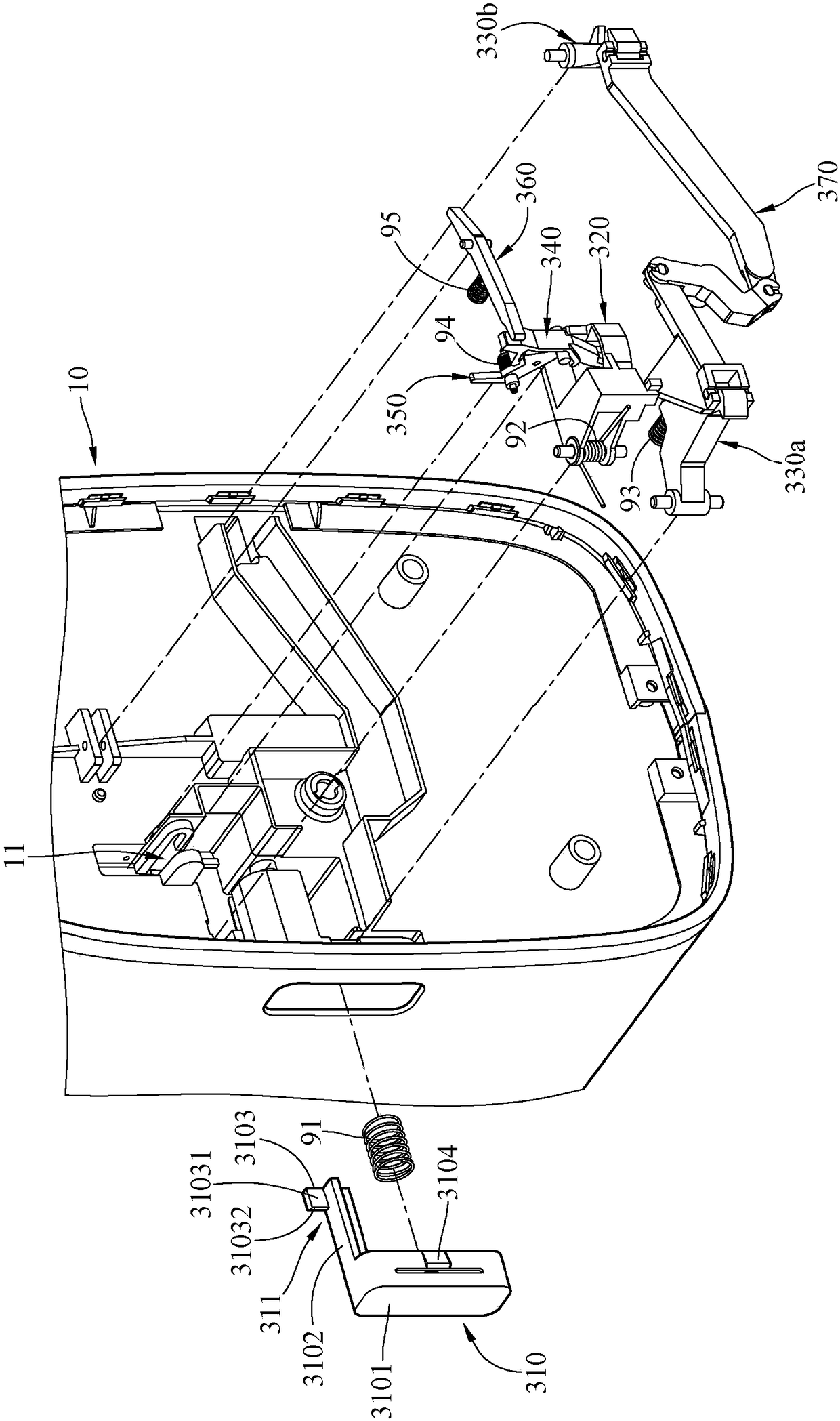
The invention discloses a dehumidifier which comprises a water tank, a main machine and a buckle mechanism. The buckle mechanism comprises a pressing piece, a shifting piece and a buckle piece. The pressing piece is arranged on the main machine and has a pressing position and a releasing position. The pressing piece comprises a pressed part, a neck part and a pressing part which together define anotch. The shifting piece is arranged on the main machine in a pivoted mode and has a dragged position and a dragging position. The buckle piece is arranged on the main machine in a pivoted mode and has a buckling position and an unbuckling position. When the pressing piece is in the pressing position, the notch of the pressing part is moved to the position above a backstop block of the shifting piece, so that the motion is canceled to enable the shifting device to rotate to the dragging position and enable the backstop block to enter the notch, so the pressing piece is dragged to the pressingposition, the buckle piece is pushed against to the unbuckling position by the shifting device when the shifting device is rotated to the dragging position so as to be disengaged from the buckle partof the water tank.

Description

Technical field [0001] The present invention relates to a dehumidifier, in particular to a dehumidifier including a buckle mechanism. [0002] The invention relates to a buckle mechanism, particularly a buckle mechanism including a pressing member. Background technique [0003] Humid air is easy to promote the growth of mold and cause many health problems. If the humidity of the environment is too high, it will also cause moisture to condense, which will make the human body feel uncomfortable, or cause the floor to be slippery and clothes are not easy to dry. Therefore, more and more people use dehumidifiers to reduce the humidity of the air in order to solve the aforementioned problems. [0004] Structurally, the dehumidifier mainly includes two parts: a body and a water tank. The body is mainly to draw indoor humid air into the machine to condense the moisture in the air into droplets and then discharge the dry air. The body is installed in the water tank. To drain the collected ...

Claims


Application Information

Patent Timeline
IPC IPC(8): F16B21/08F24F1/02
CPCF16B21/08F24F1/02E05B63/0065E05C3/16F24F3/14F24F2003/1446F24F2221/12E05B65/00E05C3/12
Inventor 朱铭灯
Owner NORM PACIFIC AUTOMATION
Learn More