Reference array element based phase correction method of radar moving object

A phase correction, moving target technology, applied in radio wave measurement systems, instruments, etc., can solve problems such as inaccurate phase correction results of target echo signals, inability to apply FM continuous wave radar, and target angle calculation errors.

Inactive Publication Date: 2018-12-11
NAT UNIV OF DEFENSE TECH
View PDF5 Cites 1 Cited by
  • Summary
  • Abstract
  • Description
  • Claims
  • Application Information

AI Technical Summary

Problems solved by technology

However, the disadvantage of this single-channel FM CW radar is that the phase of the signal received by the antenna array is not only determined by the angle of the target, but also related to the speed of the target. Usually, the phase term introduced by the target motion is a fixed constant. In the process of calculating the angle of the moving target, if the phase correction is not performed on the echo signal of the moving target, the calculation of the target angle will be wrong
The disadvantage of this method is that the target speed needs to be calculated accurately, otherwise the phase correction result of the target echo signal will be inaccurate
However, this method is only suitable for FM CW radars with multiple input and multiple output antenna arrays, and cannot be applied to single-channel FM CW radars with single-transmit and multiple-receive

Method used


Image

  • Reference array element based phase correction method of radar moving object
  • Reference array element based phase correction method of radar moving object
  • Reference array element based phase correction method of radar moving object

Examples


Embodiment Construction

[0015] The present invention will be further described below in conjunction with the accompanying drawings and embodiments.

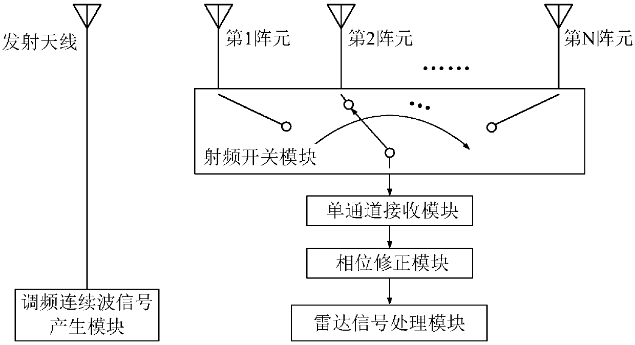
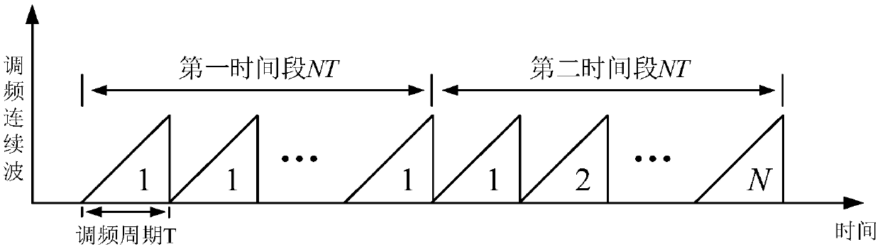
[0016] figure 1 It is a schematic diagram of the principle of the present invention applied to a single-channel FM continuous wave radar (hereinafter referred to as radar). As shown in the figure, the transmitting end of the radar includes an FM continuous wave signal generation module and a transmitting antenna, and the receiving end of the radar includes a receiving antenna array , a radio frequency switch module, a single-channel receiving module, a phase correction module and a radar signal processing module, wherein the receiving antenna array is an N-element uniform linear antenna array. figure 2 It is a schematic diagram of the switching gating sequence of the receiving antenna array of the present invention. First, the first array element of the receiving antenna array is switched and gating, that is, the reference array element, and receives s...


PUM


Abstract

The invention provides a reference array element based phase correction method of a radar moving object. According to the switching and gating sequence of a single-channel FM continuous wave radar, ina first time period in each signal reception round, a first array element of a reception antenna array is switched and gated to receive N FM periods of signals; and in a second time period in each signal reception round, all array elements in the reception antenna array are switched and gated successively from the first array element and N FM periods of signals are received. In the signal processing process, the phase of the signal received in the first period is subtracted from the phase of the signal received in the second period, a phase term introduced by target movement is eliminated, and the phase of the reception signal of the reception antenna array is corrected. According to the method, it is not required to calculate the target speed, and the method is suitable for the single-emission multi-reception single-channel FM continuous wave radar.

Description

technical field [0001] The invention belongs to the technical field of radar signal processing, and relates to a phase correction method of a radar moving target based on a reference array element. Background technique [0002] At present, radar has been widely used in different industries. Among them, FM continuous wave radar has attracted the attention of academia and industry due to its advantages of simple structure and low cost. The existing FM continuous wave radar is usually multi-channel FM continuous Wave radar, that is, each antenna needs a separate receiving channel to receive signals. As the size of the antenna array increases, the volume and cost of the system will also increase. In order to reduce the cost and system complexity of multi-channel FM CW radar, scholars proposed a single-channel FM CW radar [L. Yang and F. Zhenghe, “Switch antenna array with single receiving channel for FMCW radar,” in Proc. .Int.Symp.AntennasPropagation, Fukuoka, Japan, 2000, pp....

Claims


Application Information

Patent Timeline
Patent Type & Authority Applications(China)
IPC IPC(8): G01S7/41
CPCG01S7/41
Inventor 林沂付云起杨凯
Owner NAT UNIV OF DEFENSE TECH
Why Eureka
Try Eureka