Moving object phase correcting method of multi-input and multi-output radar

A phase correction, moving target technology, applied in the direction of reflection/re-radiation of radio waves, use of re-radiation, measurement devices, etc., can solve the problem of target angle calculation errors, inaccurate target echo signal phase correction results, etc. The effect of phase correction

Active Publication Date: 2018-08-10
NAT UNIV OF DEFENSE TECH
View PDF4 Cites 11 Cited by
  • Summary
  • Abstract
  • Description
  • Claims
  • Application Information

AI Technical Summary

Problems solved by technology

However, the disadvantage of this method is that the phase of the received signal of the virtual antenna array is not only determined by the angle of the target, but also related to the speed of the target. Usually, the phase term introduced by the target motion is a fixed constant. Item compensation, will lead to target angle calculation error
The disadvantage of this method is that the target speed needs to be calculated accurately, otherwise the phase correction result of the target echo signal will be inaccurate

Method used


Image

  • Moving object phase correcting method of multi-input and multi-output radar
  • Moving object phase correcting method of multi-input and multi-output radar
  • Moving object phase correcting method of multi-input and multi-output radar

Examples


Embodiment Construction

[0019] The present invention will be further described below in conjunction with the accompanying drawings and embodiments.

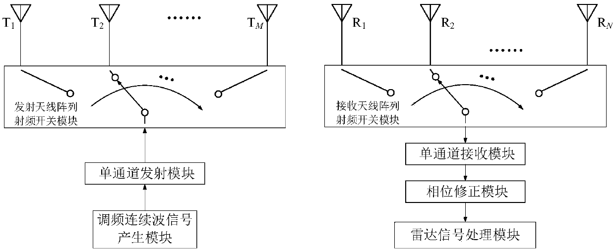
[0020] figure 1 It is a schematic diagram of the principle of the present invention applied to time-division multiplexing frequency modulation continuous wave MIMO radar (hereinafter referred to as radar). The switch module and the transmitting antenna array, the receiving end of the radar includes the receiving antenna array, the receiving antenna array RF switch module, the single channel receiving module, the phase correction module and the radar signal processing module, wherein the transmitting antenna array RF switch module is used for switching Through the array elements of the transmitting antenna array, the number of array elements of the transmitting antenna array is M, T m Indicates the mth transmitting antenna array element, m=1,2,...,M; the receiving antenna array radio frequency switch module is used to switch and gate the array elements ...


PUM


Abstract

The invention provides a moving object phase correcting method of MIMO radar. According to the technical scheme, virtual antenna arrays corresponding to the time division multiplexing frequency modulation continuous wave MIMO radar are set, the virtual antenna arrays are sequentially numbered as the first array element to the MN antenna array element according to space virtual positions, and each round of received signals are acquired according to a specific time division multiplexing time sequence; in other words, firstly, the first array element of the virtual antenna arrays receives signals, and the received signals of MN frequency modulation periods are obtained to serve as the first time period of each round of received signals; then the virtual antenna arrays receive the signalsaccording to the sequence from the first array element to the MN array element, and the signals serve as a second time period of each round of received signals; in the signal processing process, subtraction between phases of the signals received at the second time periods and phases of the signals received at the first time periods is carried out, and the phases of the received signals are corrected. The target speed does not need to be calculated, redundant virtual array elements do not need to be designed, and phase correction of a moving object is achieved under the condition that the angle resolution of the radar is not reduced.

Description

technical field [0001] The invention belongs to the technical field of radar signal processing, and relates to a phase correction method for a moving target of a MIMO (Multiple Input Multiple Output) radar. Background technique [0002] Compared with single-input multiple-output radar, MIMO radar can use a smaller-scale antenna array to realize a larger-caliber virtual antenna array, thereby improving the angular resolution of the radar. Frequency modulation continuous wave radar has the characteristics of low cost, simple structure and small size. At the same time, it can accurately measure the distance and speed of the target. Combined with the application of antenna array, it can realize the angle measurement of the target. The frequency-modulated continuous wave MIMO radar combines the advantages of the above two radars, and uses a simpler structure antenna array to achieve higher radar angular resolution. [0003] Time-division multiplexing frequency modulation continu...

Claims


Application Information

Patent Timeline
Patent Type & Authority Applications(China)
IPC IPC(8): G01S7/40G01S13/50
CPCG01S7/4004G01S13/50
Inventor 林沂付云起杨凯
Owner NAT UNIV OF DEFENSE TECH
Why Eureka
Try Eureka