Optical experiment demonstration structure applied to physics teaching

An optical and experimental technology, applied in the field of optical experimental demonstration structure, can solve the problems that the light source of the demonstrator cannot be fixed, the height of the demonstrator cannot be adjusted, etc., and achieve the effect of improving teaching quality, reasonable design structure, and efficient teaching demonstration effect.

CN108986616AInactive Publication Date: 2018-12-11张澄昕
3 Cites 3 Cited by

Patent Information

Authority / Receiving Office
CN · China
Patent Type
Applications(China)
Current Assignee / Owner
Publication Date
2018-12-11
Estimated Expiration
Not applicable · inactive patent

Smart Images

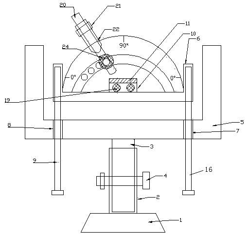
  • Figure 1
    Figure 1
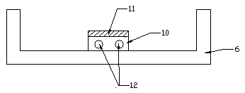
  • Figure 2
    Figure 2
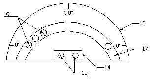
  • Figure 3
    Figure 3
Patent Text Reader

Abstract

The invention belongs to the technical field of application of teaching apparatuses, and specifically discloses an optical experiment demonstration structure applied to physics teaching. The structureis formed by a bottom elevation adjustment assembly and a refraction demonstration assembly used in cooperation with the bottom elevation adjustment assembly. The beneficial effects of the optical experiment demonstration structure applied to physics teaching are that the design structure is reasonable, certain height adjustment can be performed through an inner spiral adjusting sleeve, an auxiliary outside thread adjusting column and a positioning screw rod during demonstration, if a requirement is not met, height adjustment is performed again through a first thread adjusting hole, a secondthread adjusting hole, a first elevation adjusting screw rod and a second elevation adjusting screw rod, stable limitation of the incident angle for a small electric torch of a light-emitting source can be performed through additionally provided components including an arc groove, first auxiliary internal thread positioning holes, a second auxiliary internal thread positioning hole and an auxiliary positioning screw rod, the unity of the demonstration incident angle is improved, high-efficiency teaching demonstration effect can be guaranteed, and the teaching quality is improved.
Need to check novelty before this filing date? Find Prior Art

Description

technical field

[0001] The invention belongs to the technical field of teaching instrument application, and specifically relates to an optical experiment demonstration structure applied to physics teaching, which is suitable for physics teaching demonstration operations, realizes efficient and stable light reflection teaching, and at the same time facilitates intuitive demonstration and observation and improves student performance. Learning enthusiasm, learning efficiency, improve teaching quality. Background technique

[0002] Light reflection is a physical phenomenon in nature. When light hits the interface between two media, some of the light changes its propagation direction and returns to the original medium to continue to propagate. This light reflection phenomenon is called light reflection.

[0003] The phenomenon of reflection of light is universal. When light hits the surface of any object, reflection will occur (except for the absolute black body, which can absorb...

Examples

Embodiment

[0018] Such as figure 1 , figure 2 , image 3 and Figure 4 The shown optical experiment demonstration structure applied to physics teaching is composed of a bottom lifting adjustment component and a refraction demonstration component used in conjunction with the bottom lifting adjustment component; the bottom lifting adjustment component includes a base 1 and is arranged on the base 1 The internal screw adjusting sleeve 2 on the top, and the auxiliary external thread adjusting column 3 used in conjunction with the internal screw adjusting sleeve 2, wherein the internal screw adjusting sleeve 2 and the auxiliary external thread adjusting column 3 are provided with matching positioning holes and passed through The positioning screw 4 is connected; the refraction demonstration assembly includes a U-shaped positioning clamp 5 arranged at the end of the auxiliary external thread adjustment column 3, and an auxiliary U located in the U-shaped positioning clamp 5 and matched with...