
Stationary part and motor

A technology of static parts and motors, applied in the field of motors, to achieve the effect of easy connection

Inactive Publication Date: 2018-12-11
NIDEC TECHNO MOTOR CORP
View PDF1 Cites 1 Cited by
  • Summary
  • Abstract
  • Description
  • Claims
  • Application Information

AI Technical Summary

Problems solved by technology

However, there is a slight gap between the wire drawn from the coil to the terminal pin and the mold

Method used


Image

  • Stationary part and motor
  • Stationary part and motor
  • Stationary part and motor

Examples


Embodiment Construction

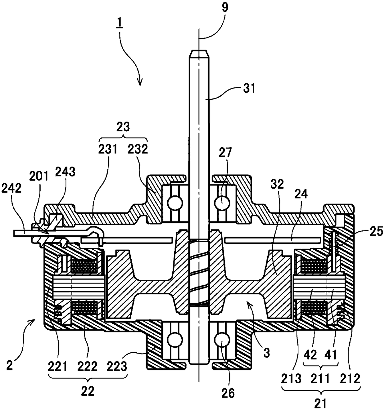
[0014] Below, while referring to the attached Figure 1 Exemplary embodiments of the present invention will be described. In addition, in this application, the direction parallel to the central axis of the motor is referred to as "axial direction", the direction perpendicular to the central axis of the motor is referred to as "radial direction", and the direction along the central axis of the motor is referred to as "radial". The direction of the arc is referred to as "circumferential". In addition, in this application, the shape and positional relationship of each part are demonstrated using the axial direction as an up-down direction, and the terminal part side as an upward direction with respect to a stator core. However, the definition of the up-down direction is not intended to limit the orientation when manufacturing and using the motor of the present invention.

[0015] figure 1 is a longitudinal sectional view of the motor 1 . This motor 1 is a so-called inner roto...


PUM


Abstract

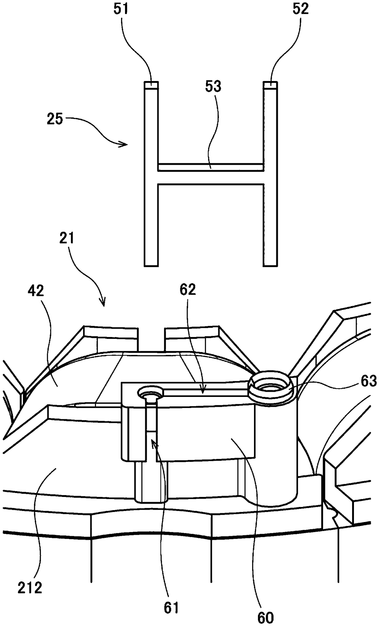
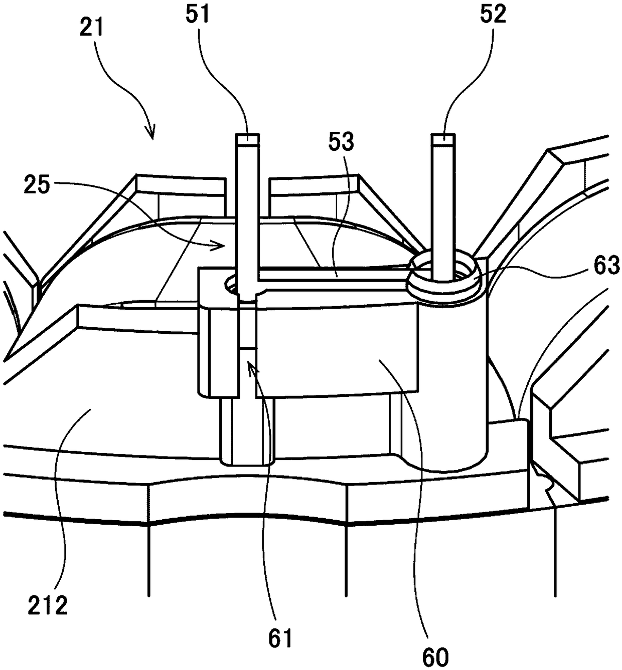
A stationary part and a motor are provided. In the stationary part, the terminal portion has: a first terminal pin; a second terminal pin located at a position apart from the first terminal pin; a connecting portion that connects the first terminal pin and the second terminal pin electrically; the first terminal pin is connected to a conductor, and a part of the second terminal pin is exposed fromthe case and connected to the conductive member.

Description

technical field [0001] The present invention relates to a stationary part of a motor and a motor having the stationary part. Background technique [0002] Conventionally, a so-called molded motor in which a stator is covered with resin is known. For example, a conventional molded motor is described in Japanese Laid-Open Publication No. H10-174338. In the structure of this publication, the winding end is connected to the terminal block via the terminal metal fitting. Also, the stator and the terminal block are covered with molded resin. [0003] However, there are cases where a terminal block or a circuit board connected to the terminals is mounted after molding. In this case, it is necessary to expose a part of the terminal from the molding resin. Therefore, for example, it is conceivable to use a mold to cover the periphery of the terminal pins during molding so that resin does not flow into the terminal pins. However, a slight gap is generated between the wire drawn f...

Claims


Application Information

Patent Timeline
IPC IPC(8): H02K3/50H02K3/38
CPCH02K3/38H02K3/50
Inventor 小谷启太
Owner NIDEC TECHNO MOTOR CORP
Learn More