
Multifunctional controllable fracture reduction fixing device

A fixed device and multi-functional technology, applied in the field of medical equipment, can solve the problems of low accuracy and easy displacement of fracture ends, and achieve the effect of complete functions, high degree of automation, and convenient and quick operation

Pending Publication Date: 2018-12-14
成都大学附属医院
View PDF0 Cites 5 Cited by
  • Summary
  • Abstract
  • Description
  • Claims
  • Application Information

AI Technical Summary

Problems solved by technology

[0005] The purpose of the present invention is: in order to solve the technical problem that the existing fracture reduction forceps have low precision when resetting and fixing the broken end of the fracture, resulting in the easy displacement of the broken end of the fracture after reduction, the present invention provides a multifunctional adjustable fracture reset fixture

Method used


Image

  • Multifunctional controllable fracture reduction fixing device
  • Multifunctional controllable fracture reduction fixing device
  • Multifunctional controllable fracture reduction fixing device

Examples


Embodiment 1

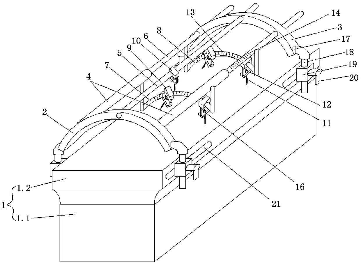
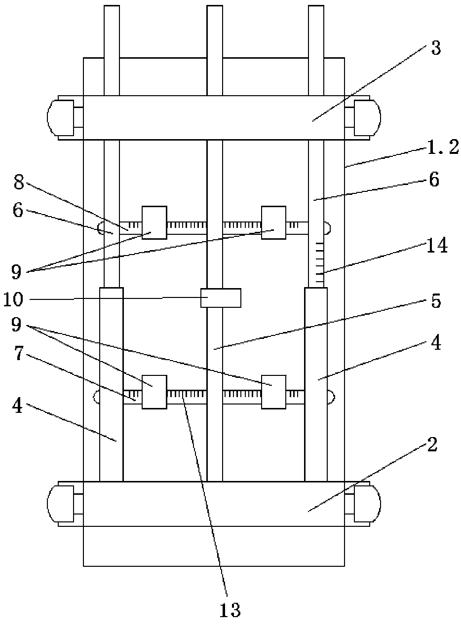
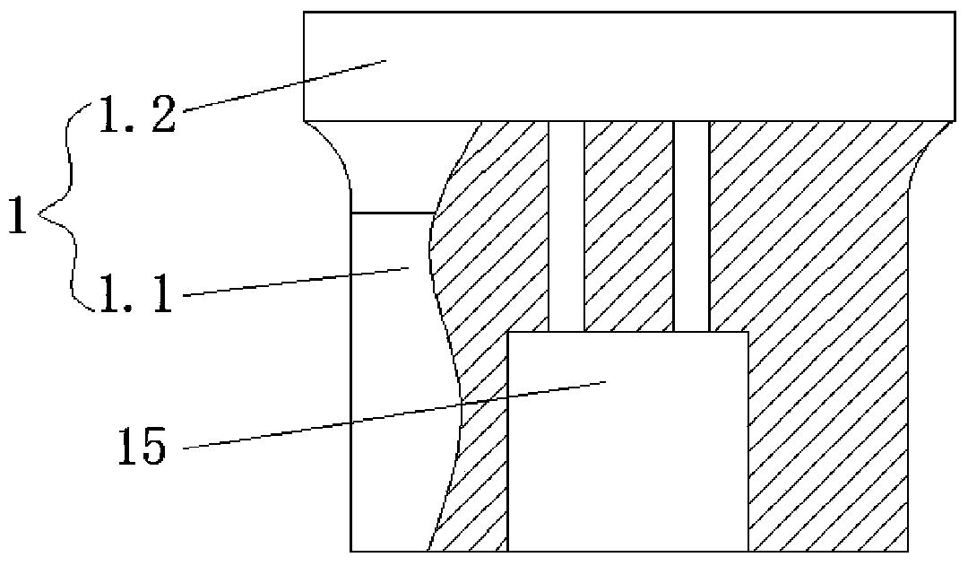
[0027] Such as Figures 1 to 2 As shown, the present embodiment provides a multifunctional adjustable fracture reduction and fixation device, which includes an operating table 1. The two ends of the top of the operating table 1 are respectively provided with a support frame A2 and a support frame B3 parallel to each other. The support frame A2 is vertically connected with Two telescopic mechanisms 4 and a connecting rod 5, the connecting rod 5 is located between the two telescopic mechanisms 4, the telescopic mechanisms 4 are connected with a telescopic rod 6, the other ends of the two telescopic rods 6 and the connecting rod 5 pass through the support frame B3, Two telescopic rods 6 and connecting rod 5 all can be slid in support frame B3, and two telescopic mechanisms 4 are connected with the arc-shaped guide rail frame A7 that is positioned at the bottom of two telescopic mechanisms 4 by poles, and two telescopic rods 6 are connected by poles and are positioned at two The a...

Embodiment 2

[0030]Such as Figures 1 to 2 As shown, the present embodiment is further optimized on the basis of Embodiment 1, specifically, the two ends of the arc-shaped guide rail frame A7 and the arc-shaped rail frame B8 are provided with rotating shafts 17, and the rotating shafts 17 are movably connected with Adjusting rod 18, the lower end of the adjusting rod 18 is covered with a slide block 19 that can slide along the side end of the operating table 1, the adjusting rod 18 can move up and down in the slide block 19, and the side end of the operating table 1 is provided with a corresponding sliding block 19. The sliding guide groove 21 and the outside of the slider 19 are provided with an adjusting wrench 20 for pressing the corresponding adjusting rod 18 .

[0031] In this embodiment, the arc-shaped rail frame A or arc-shaped rail frame B can be flipped back and forth through the rotating shaft for fine adjustment, and at the same time, the overall height of the arc-shaped rail fr...

Embodiment 3

[0033] Such as Figures 1 to 2 As shown, this embodiment is further optimized on the basis of embodiment 1, specifically, the telescopic mechanism 4 is a telescopic hydraulic cylinder or a telescopic air cylinder.

[0034] In this embodiment, the telescopic rod is pulled or pushed by the telescopic hydraulic cylinder or the telescopic air cylinder, which is convenient and quick to operate and has a high degree of automation.


PUM


Abstract

The invention discloses a multifunctional controllable fracture reduction fixing device, and relates to the technical field of medical instruments. The fixing device comprises an operating table, thetwo ends of the top of the operating table are provided with bracing frames A and B respectively, the bracing frame A is vertically connected with two telescoping mechanisms and one connecting rod, the connecting rod is positioned between the two telescoping mechanisms, the telescoping mechanisms are connected with telescoping rods respectively, the other ends of the two telescoping rods and the connecting end all penetrate the bracing frame B, an arched guide rail rack A is connected between the two telescoping mechanisms, an arched guide rail rack B is connected between the two telescoping rods, two slide guiding seats are arranged on the arched guide rail rack A, other two slide guiding seats are arranged on the arched guide rail rack B, the connecting rod is provided with a slide guiding seat A positioned between the bracing frames A and B as well as a slide guiding seat B positioned between the bracing frames A and B in the sliding manner, and Kirschner wires are arranged under each of the slide guiding seats A and B. The multifunctional controllable fracture reduction fixing device has the advantages of simple structure, accurate positioning and little operating damage.

Description

technical field [0001] The invention relates to the technical field of medical devices, and more specifically relates to a multifunctional adjustable fracture reduction and fixation device. Background technique [0002] Medical devices refer to instruments, equipment, utensils, in vitro diagnostic reagents and calibrators, materials, and other similar or related items that are directly or indirectly used on the human body, including required computer software. The effect is mainly obtained through physical means, not through pharmacological, immunological or metabolic means, or although these means are involved but only play an auxiliary role, the purpose is the diagnosis, prevention, monitoring, treatment or alleviation of diseases; the diagnosis of injury , monitoring, treatment, alleviation or functional compensation; examination, replacement, adjustment or support of physiological structures or physiological processes; life support or maintenance; pregnancy control; prov...

Claims


Application Information

Patent Timeline
Patent Type & Authority Applications(China)
IPC IPC(8): A61G13/06A61G13/10A61B17/66A61B90/11
CPCA61B17/66A61B90/11A61G13/06A61G13/10A61G2203/70A61G2210/10
Inventor 李开南王郑浩
Owner 成都大学附属医院
Learn More