
Silo clearing device

A technology of clearing and conveying devices, which is applied in the directions of packaging, transportation and packaging, loading/unloading, etc., and can solve the problem of low efficiency of residual material clearance

Pending Publication Date: 2018-12-14
秦皇岛市鸿瑞科技开发有限公司
View PDF4 Cites 1 Cited by
  • Summary
  • Abstract
  • Description
  • Claims
  • Application Information

AI Technical Summary

Problems solved by technology

[0003] In order to solve the above-mentioned problems existing in the prior art, the present invention provides a warehouse clearing device to solve the technical problem of low clearance efficiency of the remaining materials with a moderate and below compaction degree in the cylindrical silo

Method used


Image

  • Silo clearing device
  • Silo clearing device
  • Silo clearing device

Examples


Embodiment 1

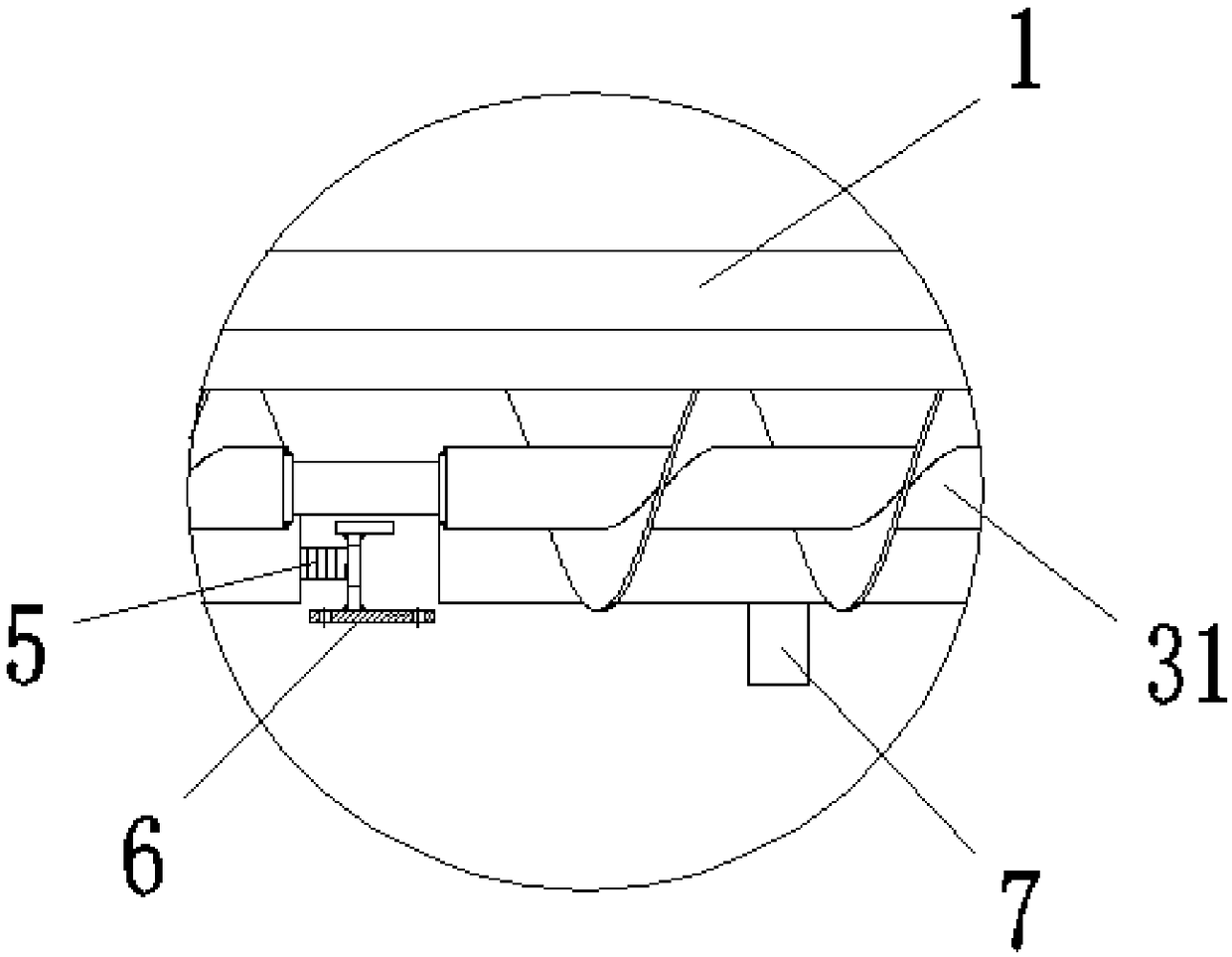
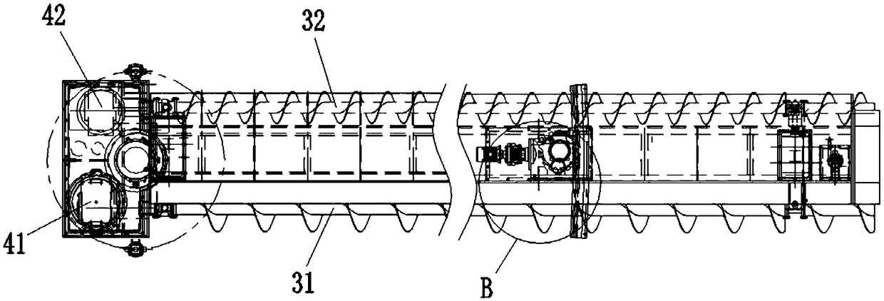
[0031] A clearing device such as Figure 1-5 As shown, it includes a frame 1 and a rotation centering device 2, the rotation centering device 2 is arranged at the end of the frame 1, and the frame 1 is also provided with a conveying device for conveying materials and for controlling the movement of the frame 1 The driving device; the conveying device includes a first auger 31 and a second auger 32, and the first auger 31 and the second auger 32 are respectively arranged on the front and rear sides of the frame 1.

[0032] Through a clearing device with the above-mentioned structure, during the clearing process, if the hardened material collapses and buries the device, causing the first auger 31 to fail to work normally, or unable to start with a load, the staff can start the second auger 32, so that The second auger 32 can clean up the material behind the clearing device, so that the clearing device can unload the load on the first auger 31 by retreating, so that the first aug...

Embodiment 2

[0044] Such as Figure 1-5 As shown, as a further optimization of the above embodiment, the clearing device also includes a control system, the control system includes a controller and a sensor, the controller is connected to the sensor, and the controller is connected to the electrical control device of the second drive motor 42 and the third drive motor 42 respectively. The electric control device of driving motor 43 is connected; Wherein, the effect of sensor is to be used for detecting the working condition of the first driving motor 41, promptly when the staff starts this clearing device, the first auger 31 can rotate normally, and sensor can the second A signal that the first auger 31 is rotating is sent to the controller; when the load on the first auger 31 increases, causing the first auger 31 to fail to work normally, that is, the first auger 31 cannot rotate during the working process At this time, the sensor will send the signal that the first auger 31 cannot work n...


PUM


Abstract

The invention belongs to the technical field of flat-bottom silo clearing equipment and particularly relates to a silo clearing device. The silo clearing device comprises a rack and a rotary centeringdevice. The rotary centering device is arranged at the end of the rack. The rack is further provided with a conveying device for conveying materials, and a driving device for controlling the rack tomove. The conveying device comprises a first auger and a second auger. The first auger and the second auger are arranged on the front side and the rear side of the rack correspondingly. In the silo clearing process, if hardened materials collapse and bury the silo clearing device and consequently the first auger cannot work normally or cannot conduct load starting, a worker can start the second auger, thus the second auger can clear away materials behind the silo clearing device, the silo clearing device can remove the load on the first auger in a retreating mode, the first auger return to theworking state, and then the silo clearing efficiency of the silo clearing device is improved.

Description

technical field [0001] The invention belongs to the technical field of clearing equipment for flat-bottomed cylindrical silos, and in particular relates to a clearing device. Background technique [0002] The existing cylindrical silo is used to store materials, and a discharge port is provided at the bottom of the silo, so that the materials near the top of the discharge port in the cylindrical silo can be discharged from the discharge port, but far away from the discharge port. The material at the outlet cannot be discharged through the discharge port, so it is necessary to use a screw cleaner to clean the material at the bottom of the silo; while the existing screw cleaner only has a screw shaft at the front end of the equipment's revolving operation, combined with the exposed cleaning material of the cleaner When the surplus grain after the mainstream of the material in the silo is hardened, the hardened material often collapses to bury the equipment during the clearing ...

Claims


Application Information

Patent Timeline
IPC IPC(8): B65G65/46B65G33/26B65G33/34
CPCB65G33/26B65G33/34B65G65/46
Inventor 韩维娜凌海明张海文李志强
Owner 秦皇岛市鸿瑞科技开发有限公司
Learn More