
Winding device for wool fabric knitting machinery

A technology of winding device and wool fabric, which is applied in the direction of winding strips, transportation and packaging, thin material processing, etc., can solve the problems of reduced service life, inconvenient mechanical installation, poor stability, etc., and achieve the effect of increasing stability

Inactive Publication Date: 2018-12-14
汕头市澄海区瑞胜毛织有限公司
View PDF10 Cites 4 Cited by
  • Summary
  • Abstract
  • Description
  • Claims
  • Application Information

AI Technical Summary

Problems solved by technology

[0006] 1. When the existing winding device is installed and fixed, the position cannot be adjusted due to the heavy mechanical weight, the flexibility is poor, and it is not convenient for mechanical installation
[0007] 2. With the existing winding device, when the reel rotates to rewind the raw material of wool fabric, the winding direction of the material is not fixed, resulting in poor stability and easy shaking
[0008] 3. With the existing winding device, when the reel collects and rewinds the wool fabric raw material, the height of the wool fabric raw material feeding is higher than that of the reel, so that the wool fabric material bears too much tension, which is prone to breakage and affects the volume. Efficiency of cartridge collection
[0009] 4. With the existing winding device, after winding a large amount of wool fabric raw materials, the reel bears a large pressure, which is easy to cause damage to the reel and reduce the service life

Method used


Image

  • Winding device for wool fabric knitting machinery
  • Winding device for wool fabric knitting machinery
  • Winding device for wool fabric knitting machinery

Examples


Embodiment Construction

[0056] The following will be combined with Figure 1-8 The present invention is described in detail, and the technical solutions in the embodiments of the present invention are clearly and completely described. Apparently, the described embodiments are only some of the embodiments of the present invention, not all of them. Based on the embodiments of the present invention, all other embodiments obtained by persons of ordinary skill in the art without making creative efforts belong to the protection scope of the present invention.

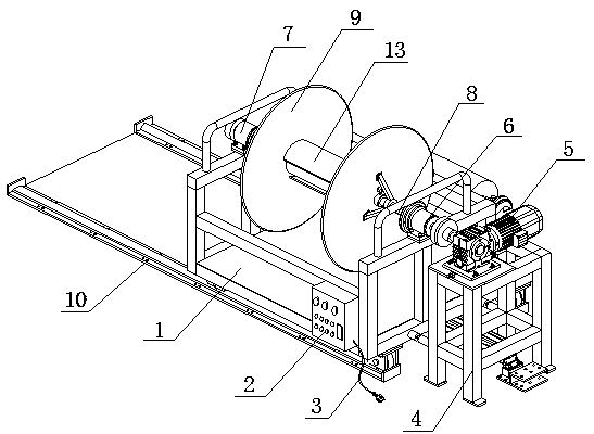
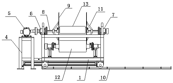
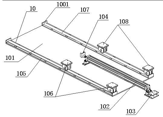
[0057] The present invention provides a winding device for a wool fabric weaving machine through improvement, including a main frame 1, a control box 2, a power cord 3, a sub-frame 4, a motor 5, a first shaft seat 6, and a second shaft Seat 7, first rotating shaft 8, reel 9, sliding mechanism 10, auxiliary fixing mechanism 11, guiding mechanism 12, buffer plate 13 and decompression mechanism 14, the rear end of control box 2 is installed on the righ...


PUM


Abstract

The invention discloses a winding device for wool fabric knitting machinery. The winding device comprises a main machine frame, a control box, a power cord, a secondary machine frame, a motor, a firstaxle seat, a second axle seat, a first rotating shaft, a reel, a sliding mechanism, an auxiliary fixing mechanism, a guiding mechanism, a buffering plate and a decompression mechanism; the rear end of the control box is mounted on the right side of the front end of the main machine frame through screws, the power cord is plugged into the bottom side of the right end of the control box, and the secondary machine frame is arranged at the right end of the main machine frame. By arranging the auxiliary fixing mechanism, a first bracket, a second bracket and a third bracket of the auxiliary fixingmechanism are mounted and fixed at the exterior of a connecting bearing in an equilateral triangle, the exterior of the reel is fixed in a triangle through a mounting plate, meanwhile, each two of the first bracket, the second bracket and the third bracket are connected and fixed through reinforcement ribs, the stability of the reel is improved, and the problem that the stability is poor, and shaking is easily caused due to the uncertain direction of the material twining when the reel rotates and winds the wool fabric raw material is solved.

Description

technical field [0001] The invention relates to the related field of knitting machine components, in particular to a winding device for wool knitting machines. Background technique [0002] The machine used to interweave two or more groups of yarns at right angles to form a fabric is called a weaving machine, and there is usually a winding device on the wool fabric weaving machine, which is used to collect the wool fabric raw materials to facilitate subsequent weaving work to achieve high efficiency. work efficiency. [0003] After searching, it is found that the invention of patent No. CN201510439477.4 discloses a textile winding device, including a textile winding device body, and a bracket arranged on the textile winding device body. There are two brackets, and the corresponding distribution On both sides, the textile winding device body is provided with a stable beam, which is arranged below the textile winding device body. The textile winding device body is provided wi...

Claims


Application Information

Patent Timeline
IPC IPC(8): B65H18/10B65H18/02B65H18/08B65H23/038
CPCB65H18/10B65H18/028B65H18/08B65H23/038B65H2701/174
Inventor 蔡道桂
Owner 汕头市澄海区瑞胜毛织有限公司
Learn More