Portable dragging moment measuring device and method based on PID control

A technology for dragging torque and measuring devices, applied in measuring devices, force/torque/power measuring instruments, torque measurement, etc., to avoid adverse effects and make the measurement process simple and accurate

Inactive Publication Date: 2018-12-14
ZHEJIANG LEAPMOTOR TECH CO LTD
View PDF6 Cites 3 Cited by
  • Summary
  • Abstract
  • Description
  • Claims
  • Application Information

AI Technical Summary

Problems solved by technology

[0004] The present invention mainly solves the problem in the prior art that the vehicle drag torque cannot be accurately measured in the vehicle state, and provides a portable drag torque measurement device and method based on PID control

Method used


Image

  • Portable dragging moment measuring device and method based on PID control
  • Portable dragging moment measuring device and method based on PID control
  • Portable dragging moment measuring device and method based on PID control

Examples


Embodiment

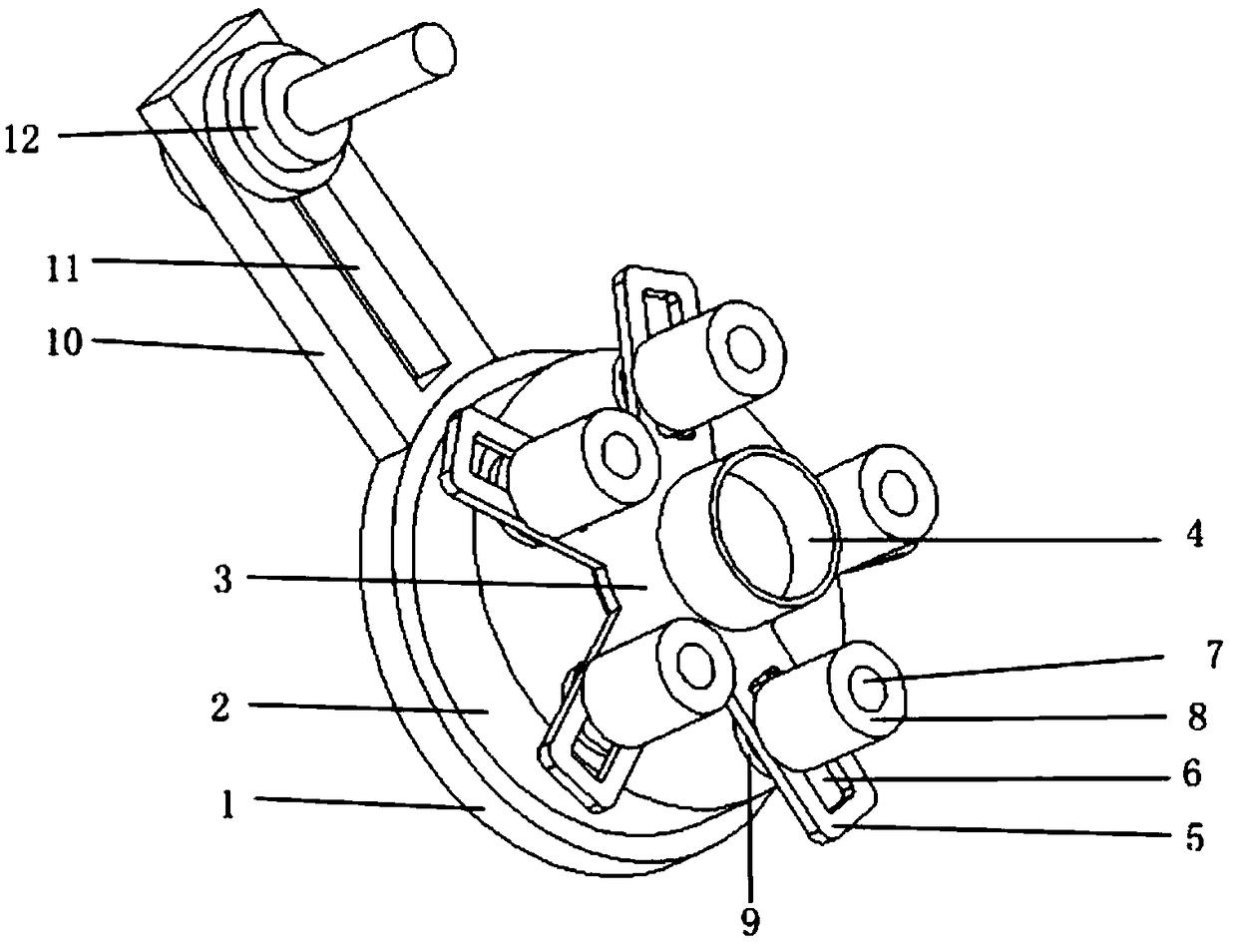
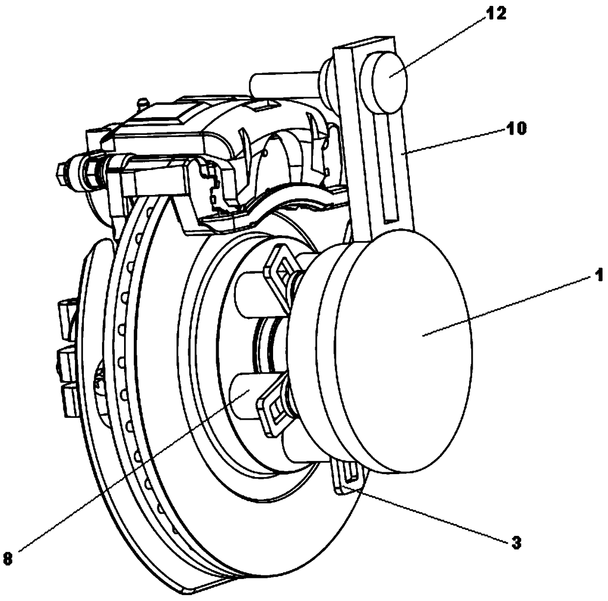
[0027] In this embodiment, a portable drag torque measurement device based on PID control, such as figure 1 As shown, it includes a torque measuring device 1, a motor 2 arranged on the torque measuring device, an adjustable mounting mechanism 3 arranged on the motor, a first adjustable mounting bracket 10 connected with the torque measuring device, and the first adjustable mounting mechanism The adjustable length locking pin 12 connected with the frame, the data display connected with the torque measuring device, the PID controller controlling the constant speed rotation of the motor and the vehicle controller arranged on the vehicle body; the PID controller is electrically connected with the motor, The PID controller is electrically connected to the vehicle controller, the data display is electrically connected to the torque measuring device, and the PID controller, the motor, the data display, the torque measuring device and the vehicle controller are all electrically connect...


PUM


Abstract

The invention relates to a portable dragging moment measuring device and method based on PID control. The problem that in the prior art, the vehicle dragging moment cannot be accurately measured underthe whole vehicle state is mainly solved. The portable dragging moment measuring device comprises a torque measuring device, a motor arranged on the torque measuring device, an adjustable mounting mechanism arranged on the motor, a first adjustable mounting frame connected with the torque measuring device, an adjustable length locking pin connected with the first adjustable mounting frame, and aPID controller for controlling the motor to rotate at a constant rotating speed. The PID controller is in circuit connection with the motor. The vehicle dragging moment can be accurately measured under the whole vehicle state, adverse influences of repeated dismounting and mounting on a vehicle are avoided, and thus the measuring process is easier, more convenient and more accurate.

Description

technical field [0001] The invention relates to the field of detection devices for vehicle parts, in particular to a portable drag torque measurement device and method based on PID control. Background technique [0002] The traditional braking system adopts the mode of brake pedal, booster master cylinder, brake oil pipe and wheel brake. The driver manipulates the brake pedal, and after being assisted by the booster, the oil pressure is established in the brake master cylinder, and the brake oil pipe transmits the oil pressure to the wheel brake to realize braking. Conventional brakes now include disc brakes and drum brakes. When the driver releases the brake, the brake pedal is relaxed, but the wheel brakes are still fully or partially in the braking state, and the brake cannot be released quickly, which will cause the brake drum (disc) to heat up and the driving resistance to increase. The most commonly used method is bench measurement. The existing brake drag torque me...

Claims


Application Information

Patent Timeline
Patent Type & Authority Applications(China)
IPC IPC(8): G01L5/28G01L3/00
CPCG01L3/00G01L5/28
Inventor 宋建勋
Owner ZHEJIANG LEAPMOTOR TECH CO LTD
Why Eureka
Try Eureka