Touch driving method, touch panel and touch display device

A technology of touch panel and touch drive, which is applied in the direction of instruments, electrical digital data processing, and the input/output process of data processing. Work normally, ensure reliability, and benefit from the effect of narrow bezel design

Pending Publication Date: 2018-12-14
SHENZHEN DEMINGLI ELECTRONICS
View PDF0 Cites 5 Cited by
  • Summary
  • Abstract
  • Description
  • Claims
  • Application Information

AI Technical Summary

Problems solved by technology

[0004] The purpose of the present invention is to solve the problem that the voltages actually applied to the transmitting electrodes are different due to different resistances in the touch panel of the above prior art, so that the induction signal of the receiving electrode at the near end is too large and the induction signal at the far end is too small problem, a touch driving method, a touch panel and a touch display device are proposed, which can effectively improve the problem, ensure the normal operation of the controller, and improve product performance

Method used


Image

  • Touch driving method, touch panel and touch display device
  • Touch driving method, touch panel and touch display device

Examples


Embodiment 1

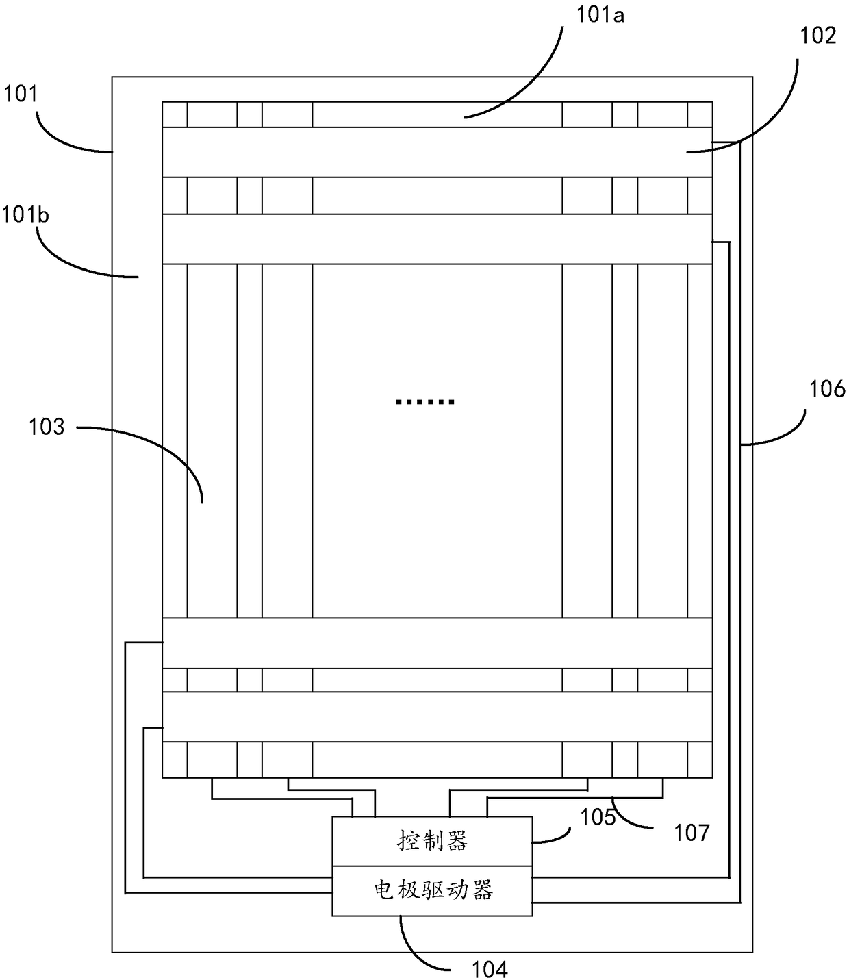
[0042] refer to figure 1 , this embodiment provides a touch panel, including a substrate 101;

[0043] The substrate 101 includes a touch area 101a and a non-touch area 101b surrounding the touch area 101a;

[0044] The touch area 101a is provided with a plurality of first touch electrodes 102 arranged along a first direction and a plurality of second touch electrodes 103 arranged along a second direction, and the first direction is perpendicular to the second direction;

[0045] In the first direction, an electrode driver 104 and a controller 105 are arranged in a non-touch area on one side of the substrate 101;

[0046] A plurality of first touch electrodes 102 are connected to the electrode driver 104 through a plurality of first signal lines 106, and a plurality of second touch electrodes 103 are connected to a controller 105 through a plurality of second signal lines 107;

[0047] The electrode driver 104 is also connected with the controller 105;

[0048] The controll...

Embodiment 2

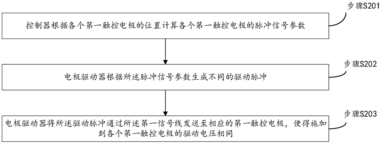
[0063] refer to figure 2 , this embodiment provides a touch driving method, which is applied to the touch panel as described in Embodiment 1, and the method includes:

[0064] Step S201, the controller calculates the pulse signal parameters of each first touch electrode according to the position of each first touch electrode;

[0065] Step S202, the electrode driver generates different driving pulses according to the pulse signal parameters;

[0066] Step S203 , the electrode driver sends the driving pulse to the corresponding first touch electrodes through the first signal line, so that the driving voltages applied to the first touch electrodes are the same.

[0067] For the specific structure of the touch panel, please refer to Embodiment 1, which will not be repeated here.

[0068] Further, the pulse signal parameters include pulse voltage value and pulse width.

[0069] Further, calculating the pulse voltage value includes:

[0070] The minimum driving voltage of the ...

Embodiment 3

[0092] This embodiment provides a touch display device, including the touch panel as described in the first embodiment.


PUM


Abstract

The invention provides a touch driving method, a touch panel and a touch display device. Pulse signal parameters required are calculated according to the positions of the respective emitting electrodes, and different driving pulses are generated according to different pulse signal parameters and sent to corresponding first touch electrodes, so that signal compensation can be carried out for the first touch electrodes remote from the controller and the driving voltages finally applied to the first touch electrodes are the same; the inductive signal intensities of the second touch electrodes areequal, the normal operation of the controller is ensured, and the reliability of the touch control is ensured. In addition, the influence of the first signal line resistance can be overcome, which isadvantageous to the narrow frame design of the touch panel.

Description

technical field [0001] The present invention relates to the technical field of touch display, in particular to a touch driving method, a touch panel and a touch display device. Background technique [0002] The capacitive touch screen is a human-computer interaction input device on the surface of the display, and is widely used due to its excellent performance. [0003] It uses the principle of inductive capacitance to obtain interactive information such as pressing and scribing, so it is called capacitive touch screen. In order not to affect the effect of the display, the capacitive touch screen uses transparent resistive materials such as indium tin oxide (ITO for short) to make multiple rows and columns of intersecting electrodes to obtain interactive information such as pressing and scribing. interactive information. Generally, the row electrode is used as the transmitting electrode (TX for short), and the column electrode is used as the receiving electrode (RX for sho...

Claims


Application Information

Patent Timeline
Patent Type & Authority Applications(China)
IPC IPC(8): G06F3/044G06F3/041
CPCG06F3/0416G06F3/044
Inventor 田华孙铁军
Owner SHENZHEN DEMINGLI ELECTRONICS
Why Eureka
Try Eureka