
Automatic stirring device of automatic cooking machine

An automatic stirring and automatic cooking technology, which is applied to the support of the cooker, cooking utensils, plug-ins, etc., can solve the problems that the lid of the frying pan cannot be sealed, the stirring rod is troublesome to disassemble, and it is inconvenient to clean, so as to achieve convenient layout design and easy Simple and convenient cleaning work and disassembly

Pending Publication Date: 2018-12-18
广州市易趣科技有限公司
View PDF0 Cites 1 Cited by
  • Summary
  • Abstract
  • Description
  • Claims
  • Application Information

AI Technical Summary

Problems solved by technology

[0002] At present, existing automatic cooking machines generally use a motor to drive a stirring rod with a certain shape to realize the stir-frying action. Although the shapes are different, there are mainly the following implementation methods in summary: At the top, the stirring rod in the pot body is driven by the transmission rod to rotate to realize stir frying. In this way, the transmission rod penetrates into the pot body downwards, causing the lid of the frying pot to not be sealed, and the pot cannot be opened in the left and right directions; 2. The driving mechanism is in the pot body The bottom of the pot is driven by the transmission rod to rotate the stirring rod in the pot to achieve stir frying. In this way, the transmission rod penetrates into the pot body upwards, and the stirring mechanism is connected with the pot, which is not easy to clean; 3. The cavity formed by the pot body and cover Rotating the stirring rod up and down in the body to turn over to realize stir-frying, this way will cause the vegetables to be turned over to the top of the pot, and the stirring rod is troublesome to disassemble and clean. Therefore, the present invention proposes an automatic stirring device for an automatic cooking machine to solve the problem. Problems in prior art

Method used


Image

  • Automatic stirring device of automatic cooking machine
  • Automatic stirring device of automatic cooking machine
  • Automatic stirring device of automatic cooking machine

Examples


Embodiment Construction

[0019] In order to deepen the understanding of the present invention, the present invention will be further described below in conjunction with the examples, which are only used to explain the present invention, and do not constitute a limitation to the protection scope of the present invention.

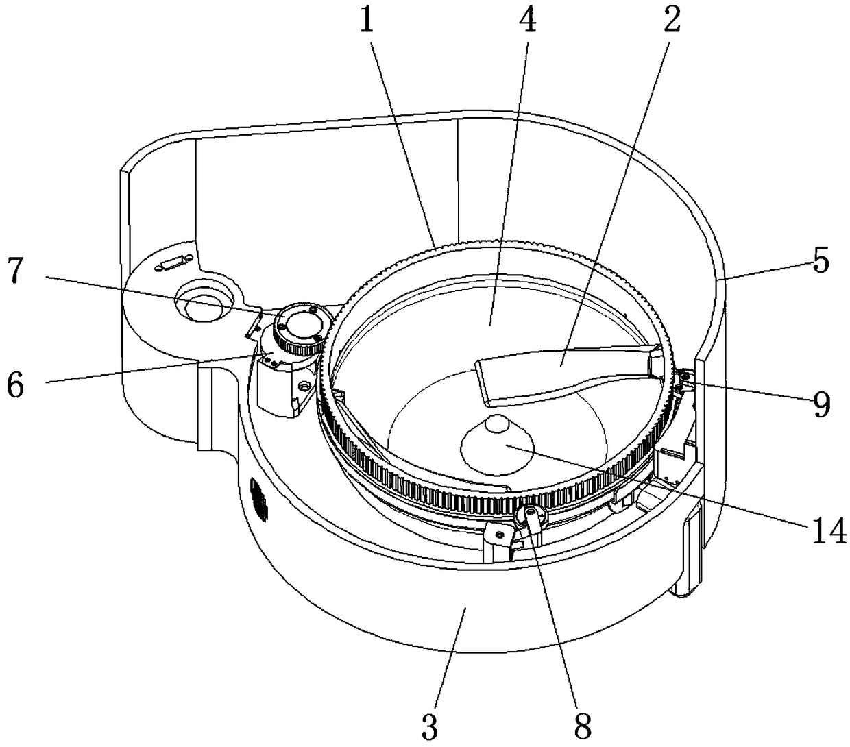
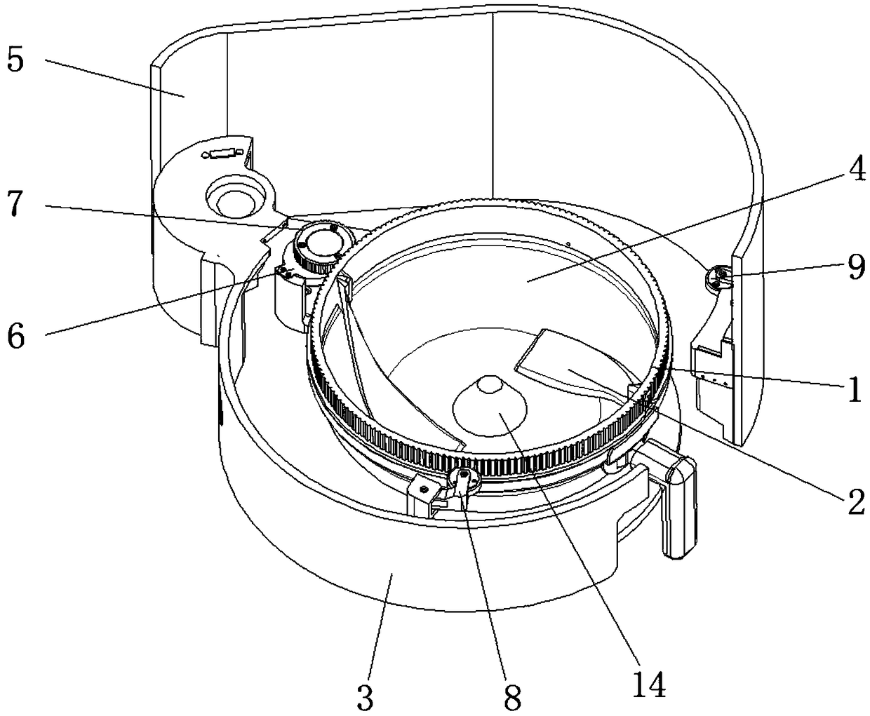
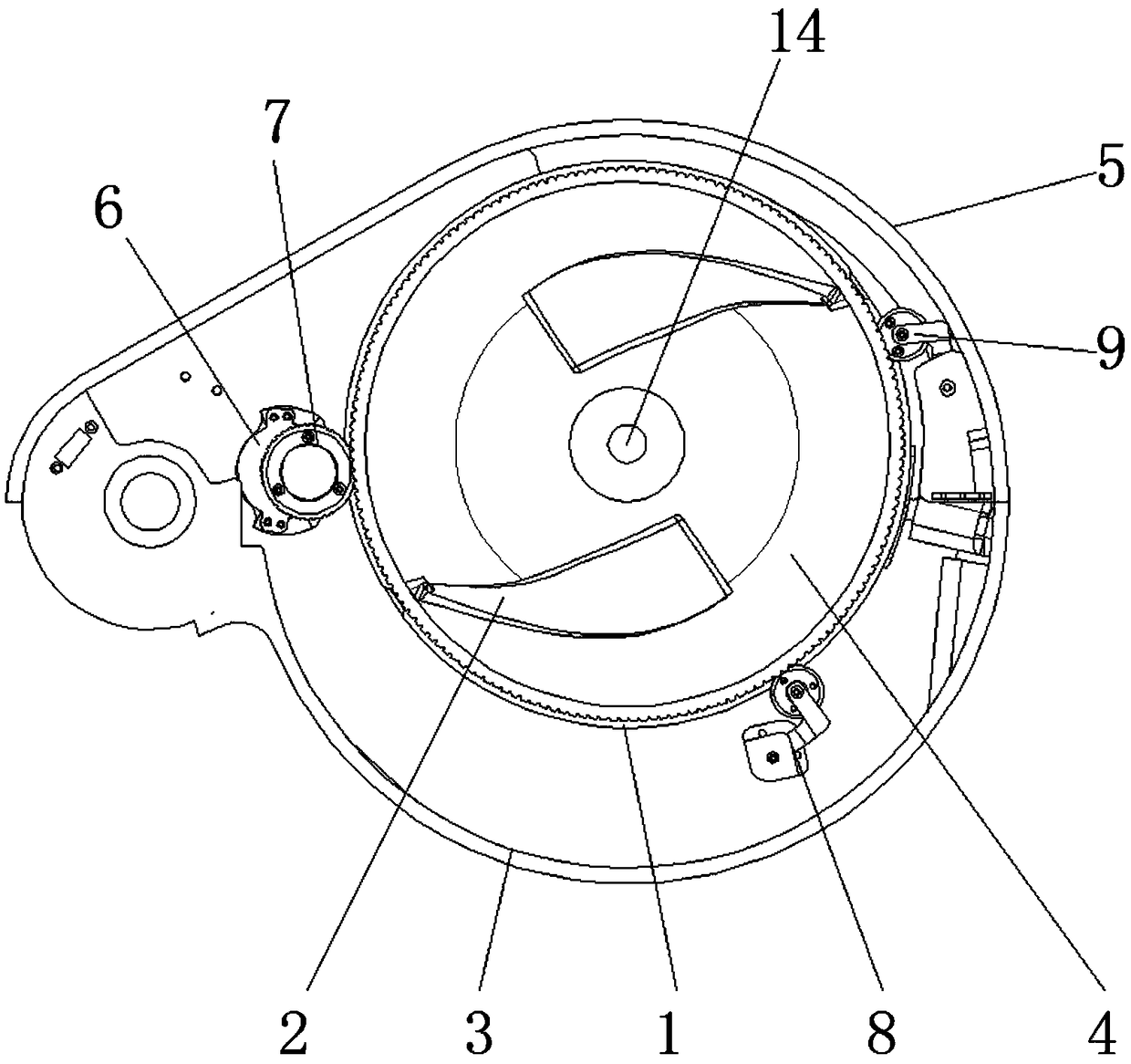
[0020] according to figure 1 , 2 , 3, 4, 5, and 6, the present embodiment provides an automatic stirring device for an automatic cooking machine, including a stirring ring 1 and a stirring arm 2, and the stirring arm 2 is installed on the inside of the stirring ring 1, and the stirring The outside of the ring 1 is provided with external teeth, the bottom of the stirring ring 1 is provided with a pot seat 3, and the pot seat 3 is provided with a pot 4, the top of the pot 4 is installed with the stirring ring 1, and the pot seat 3 One side is provided with machine base 5, and described pot 4 is fixed by the closure of pot base 3 and machine base 5, and one side on described pot base 3...


PUM


Abstract

The invention discloses an automatic stirring device of an automatic cooking machine. The device comprises a stirring ring and a stirring arm, the stirring arm is arranged on the inner side of the stirring ring, outer teeth are arranged on the outer side of the stirring ring, and a pot base is arranged under the stirring ring; a pot is arranged on the pot base, and the stirring ring is arranged onthe upper portion of the pot; a machine base is arranged on one side of the pot base, the pot and the machine base are closed and fixed through the pot base, a motor base is arranged on one side of the pot base, a motor is installed on the motor base, and a driving wheel is arranged at the output end above the motor. The stirring arm is fixed to the stirring ring, the stirring ring is placed on the pot, the stirring ring and the pot are arranged on the pot base together, the pot and the stirring ring are tightly pressed, and meanwhile, the driving wheel presses and makes contact with the stirring ring to make the stirring ring to rotate and conduct stir-frying, so that the structure prevents a stirring mechanism from directly invading into space in the pot from the pot top or the pot bottom; the top can be sealed, the structure is simple and stable, and the layout design of the whole machine is facilitated.

Description

technical field [0001] The invention relates to the technical field of cooking equipment, in particular to an automatic stirring device for an automatic cooking machine. Background technique [0002] At present, existing automatic cooking machines generally use a motor to drive a stirring rod with a certain shape to realize the stir-frying action. Although the shapes are different, there are mainly the following implementation methods in summary: At the top, the stirring rod in the pot body is driven by the transmission rod to rotate to realize stir frying. In this way, the transmission rod penetrates into the pot body downwards, causing the lid of the frying pot to not be sealed, and the pot cannot be opened in the left and right directions; 2. The driving mechanism is in the pot body The bottom of the pot is driven by the transmission rod to rotate the stirring rod in the pot to achieve stir frying. In this way, the transmission rod penetrates into the pot body upwards, an...

Claims


Application Information

Patent Timeline
IPC IPC(8): A47J36/16A47J36/34
CPCA47J36/165A47J36/34
Inventor 罗志南邹金灿林玮乔
Owner 广州市易趣科技有限公司
Learn More