Universal inertial focus microfluidic chip

A microfluidic chip and inertial technology, applied in the field of microfluidics, can solve problems such as lack of versatility, increase in types and quantities of microfluidics chips, lack of compatibility with different sorting applications, etc., to save the number of chips and control The effect of manufacturing and application costs

Pending Publication Date: 2018-12-18
SHENZHEN GENFLOW TECH CO LTD
View PDF4 Cites 1 Cited by
  • Summary
  • Abstract
  • Description
  • Claims
  • Application Information

AI Technical Summary

Problems solved by technology

[0004] However, the existing inertial focusing microfluidic chips can only meet the needs of a single type of sorting, and do not have compatibility with different sorting applications. The lack of versatility increases the types and quantities of microfluidic chips required. The cost of fine sorting is greatly increased, which is not conducive to mass production and application

Method used


Image

  • Universal inertial focus microfluidic chip
  • Universal inertial focus microfluidic chip
  • Universal inertial focus microfluidic chip

Examples


Embodiment 1

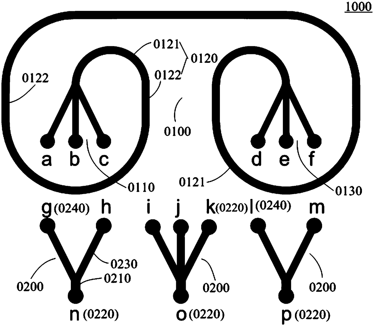
[0035] Please refer to Figure 1~2 , this embodiment discloses a specific structure of a general-purpose inertial focusing microfluidic chip 1000, the chip includes a main functional unit 0100 and at least one kind of flow splitting unit 0200, which are used to realize different forms of inertial focusing Dean vortex structures compatiblely, satisfying different Types of fluids for sorting applications.

[0036] The main functional unit 0100 includes a first exchange port 0110 , a vortex channel 0120 and a second exchange port 0130 connected in sequence, and the first exchange port 0110 and the second exchange port 0130 are located at two ends of the vortex channel 0120 .

[0037] The first exchange end 0110 includes at least three fluid inlets (such as the first inlet a, the second inlet b, and the third inlet c) connected to the outer, middle, and inner sides of the end (which may be the input end) of the vortex channel 0120 respectively. ), for injecting fluid from differe...

Embodiment 2

[0058] On the basis of Embodiment 1, this embodiment further introduces a specific application of the general inertial focusing microfluidic chip 1000 .

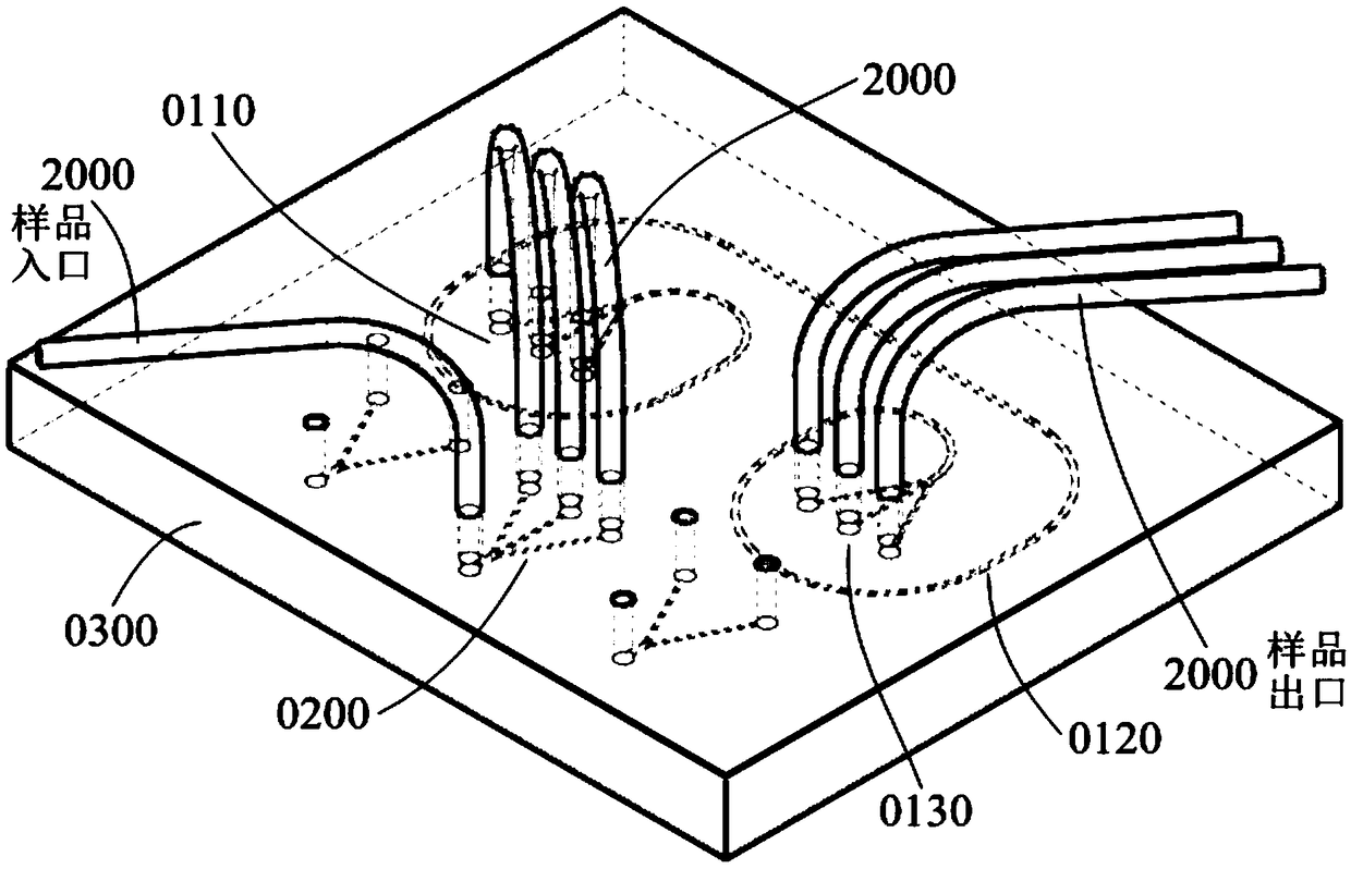
[0059] Please refer to figure 1 and image 3 , in this embodiment, the number of the branching unit 0200 is one and is a four-way branching structure, including a first dry port o and three first branching ports (i, j, k). Wherein, the first dry interface o is used to connect with the sample source to introduce the sample flow. Wherein, the first sub-ports i, j, k are correspondingly connected to the first inlet a, the second inlet b, and the third inlet c through the pipeline 2000 . At the same time, the first outlet d, the second outlet e and the third outlet f of the main functional unit 0100 respectively output the sorting results through the pipeline 2000 .

[0060] In application, the sample flow flows in from the first dry interface o, and is divided by the flow splitting unit 0200 to form three streams, which are ...

Embodiment 3

[0062] On the basis of Embodiment 1, this embodiment further introduces a specific application of the general inertial focusing microfluidic chip 1000 .

[0063] Please refer to figure 1 and Figure 4 , in this embodiment, the number of flow splitting units 0200 is two, and all of them have a three-way split structure. The first branching unit includes a second dry port n and two second branch ports (g, h) for introducing sheath fluid; the second branching unit includes a third dry port p and two third branch ports (l, m), used to output sorting results.

[0064] Wherein, the third inlet c of the first exchange port 0110 is connected to the sample source through a pipeline 2000 to introduce a sample flow. The second dry port n is connected to the sheath flow pump to input the sheath flow liquid. The second ports g and h are respectively connected to the first inlet a and the second inlet b through the pipeline 2000 , and the sheath fluid is input into the vortex channel 01...


PUM


Abstract

The invention provides a universal inertial focus microfluidic chip, which comprises a main functional unit and at least one flow division unit, wherein the main functional unit comprises a first exchange end, an vortex passage and a second exchange end in sequential connectioncommunication; the vortex passage is used for realizing the Dean vortex of fluid; the first exchange end comprises at least three fluid inlets which are respectively communicated with the outer side, the middle part and the inner side of the vortex passage; the second exchange end comprises at least three fluid outlets which are respectively communicated with the inner side, the middle part and the outer side of the end part of the other end of the vortex passage; the flow division unit comprises a main exchange endand a plurality of flow division exchange ends respectively communicated with the main exchange end; different kinds of flow division units have different quantities of flow division exchange ends. The universal inertial focus microfluidic chip provided by the invention has universality and compatibility on different sorting application structures; the required chip quantity is reduced; the manufacturing and application cost is effectively controlled.

Description

technical field [0001] The invention belongs to the field of microfluidic technology, and specifically relates to a general inertial focusing microfluidic chip. Background technique [0002] As a kind of high-throughput sorting technology, inertial focusing microfluidic technology has broad application prospects. Breaking through the traditional cognition that micro-scale flow has a low Reynolds number and negligible inertia, the inertial focusing microfluidic technology extends the inertial effect of macroscopic flow to the field of microfluidics, effectively realizing the high-throughput and precise control of micro-particles . [0003] Among the sorting methods based on physical features, inertial focusing microfluidic technology is known for its purely physical method relying on hydrodynamics that does not destroy the integrity of the sample, the flow rate between laminar flow and turbulent flow, and the flow rate significantly larger than the sample particles. The cro...

Claims


Application Information

Patent Timeline
Patent Type & Authority Applications(China)
IPC IPC(8): B01L3/00
CPCB01L3/502753
Inventor 康宁锴
Owner SHENZHEN GENFLOW TECH CO LTD
Why Eureka
Try Eureka