
Rapid treatment equipment for casting surface

A technology for processing equipment and castings, which is applied in the field of rapid processing equipment for casting surfaces, can solve problems such as low work efficiency, simple structure, and inability to remove dust, and achieve the effect of increasing types and improving efficiency

Inactive Publication Date: 2018-12-18
江苏冠开实业发展有限公司
View PDF3 Cites 12 Cited by
  • Summary
  • Abstract
  • Description
  • Claims
  • Application Information

AI Technical Summary

Problems solved by technology

[0002] In the field of casting equipment, there are a variety of processing equipment. The surface treatment equipment of castings is one of the commonly used equipment, which can be used to polish, paint or degrease the surface of castings; at the same time, casting surface treatment equipment also includes casting dust removal Equipment, which is used to remove dust on the surface of castings, while the structure of traditional casting dust removal devices is too simple, only using manual air blowers to remove dust from castings, the work efficiency is very low, and it can no longer meet the needs of today's society
[0003] At present, most of the castings are cleaned by blowing air from the fan. When the dust on the surface of the casting is relatively firm, the dust cannot be completely removed by blowing close to it, resulting in low cleaning efficiency. In addition, the current cleaning does not collect the dust. It is also easy to cause the flying of dust, which reduces the quality of the cleaning environment

Method used


Image

  • Rapid treatment equipment for casting surface
  • Rapid treatment equipment for casting surface
  • Rapid treatment equipment for casting surface

Examples


Embodiment Construction

[0021] The following will clearly and completely describe the technical solutions in the embodiments of the present invention with reference to the accompanying drawings in the embodiments of the present invention. Obviously, the described embodiments are only some, not all, embodiments of the present invention. Based on the embodiments of the present invention, all other embodiments obtained by persons of ordinary skill in the art without making creative efforts belong to the protection scope of the present invention.

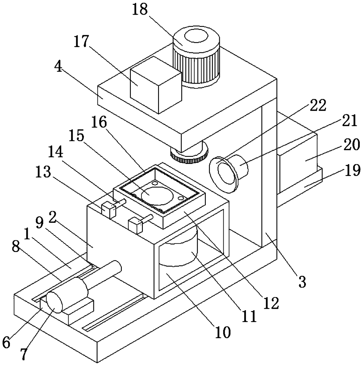
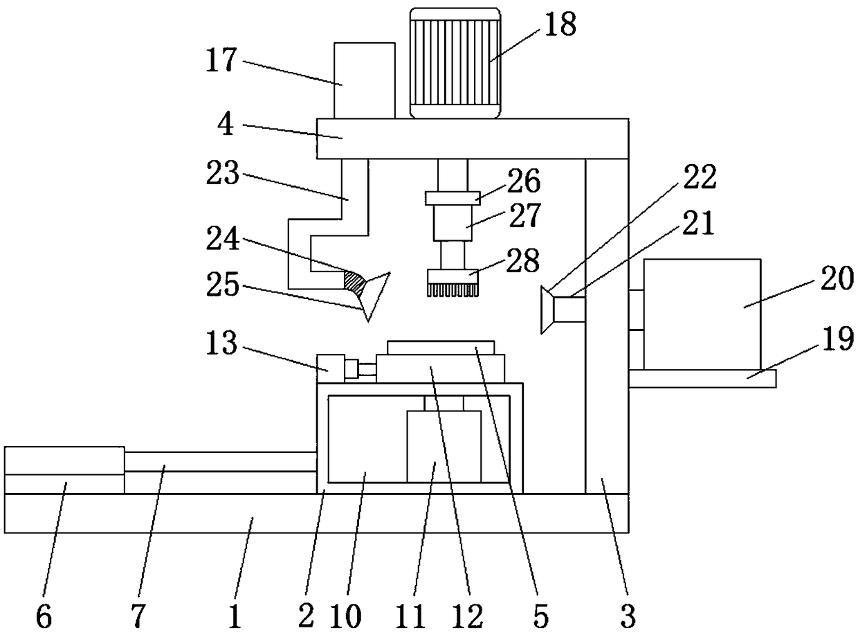
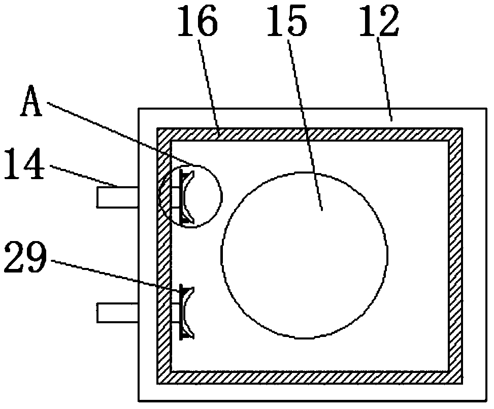
[0022] The present invention provides such Figure 1-4 A casting surface rapid processing equipment shown includes a base 1, a side support plate 3, a top plate 4 and a support frame 2, a vertical side support plate 3 is welded on the right side of the upper end surface of the base 1, and the The top of the side support plate 3 is welded and fixed to the right side of the bottom end of the top plate 4, and the base 1, the side support plate 3 and the top plate...


PUM


Abstract

The invention discloses rapid treatment equipment for a casting surface. The rapid treatment equipment comprises a base, a lateral supporting plate, a top plate and a supporting frame. The vertical lateral supporting plate is welded on the right side of the upper end face of the base, and the top end of the lateral supporting plate and the right side of the bottom end of the top plate are fixed with welding. The supporting frame is arranged on the base and is of a box-shaped structure with an internal channel, a casting fixing box used for storing a casting is arranged on the supporting frame,the inner wall of the casting fixing box is covered with rubber plates, and a clamping mechanism used for clamping the casting is arranged on one side of the casting fixing box. A cleaning mechanismused for cleaning the casting is arranged above the casting fixing box, and a dust suction mechanism used for treating dust after cleaning is arranged on the other side of the casting fixing box. Through the cleaning mechanism, the clamping mechanism and the dust suction mechanism of the rapid treatment equipment for the casting surface, the cleaning efficiency of the casting surface is improved,meanwhile the dust can be conveniently sucked after cleaning, and cleanness of the casting surface is guaranteed.

Description

technical field [0001] The invention belongs to the technical field of casting equipment, and in particular relates to a casting surface rapid processing equipment. Background technique [0002] In the field of casting equipment, there are a variety of processing equipment. The surface treatment equipment of castings is one of the commonly used equipment, which can be used to polish, paint or degrease the surface of castings; at the same time, casting surface treatment equipment also includes casting dust removal Equipment, which is used to remove the dust on the surface of castings, but the structure of the traditional casting dust removal device is too simple, only using manual air blower to remove dust from the castings, the work efficiency is very low, and it can no longer meet the needs of today's society. [0003] At present, most of the castings are cleaned by blowing air from the fan. When the dust on the surface of the casting is relatively firm, the dust cannot be ...

Claims


Application Information

Patent Timeline
IPC IPC(8): B08B1/00B08B1/04B08B5/02B08B13/00B08B15/04
CPCB08B5/02B08B13/00B08B15/04B08B1/32B08B1/12
Inventor 许冬
Owner 江苏冠开实业发展有限公司
Learn More