Punching mechanism adopting die with multiple form blocks

A technology of stamping mechanism and forming block, applied in the field of stamping mechanism, can solve the problems of high replacement cost, high maintenance and maintenance cost, unsatisfactory effect, etc., and achieve the effects of uniform forming force, good effect, and low replacement, maintenance and maintenance cost.

Inactive Publication Date: 2018-12-18
DONGGUAN TIANHE ELECTROMECHANICAL DEV CO LTD
View PDF10 Cites 2 Cited by
  • Summary
  • Abstract
  • Description
  • Claims
  • Application Information

AI Technical Summary

Problems solved by technology

[0002] In the existing mold mechanism, it generally uses a single cylinder for stamping. For a large mold that molds multiple products at one time, the single cylinder stamping cannot achieve uniform force, and the effect is not ideal. In addition, the existing mold is generally directly on the upper mold. There are multiple mold forming parts on the lower mold to realize multiple products forming at one time, but when some of the mold forming parts are damaged, the whole mold can only be replaced, and the replacement cost is high, and the repair and maintenance cost is high

Method used


Image

  • Punching mechanism adopting die with multiple form blocks
  • Punching mechanism adopting die with multiple form blocks

Examples


Embodiment Construction

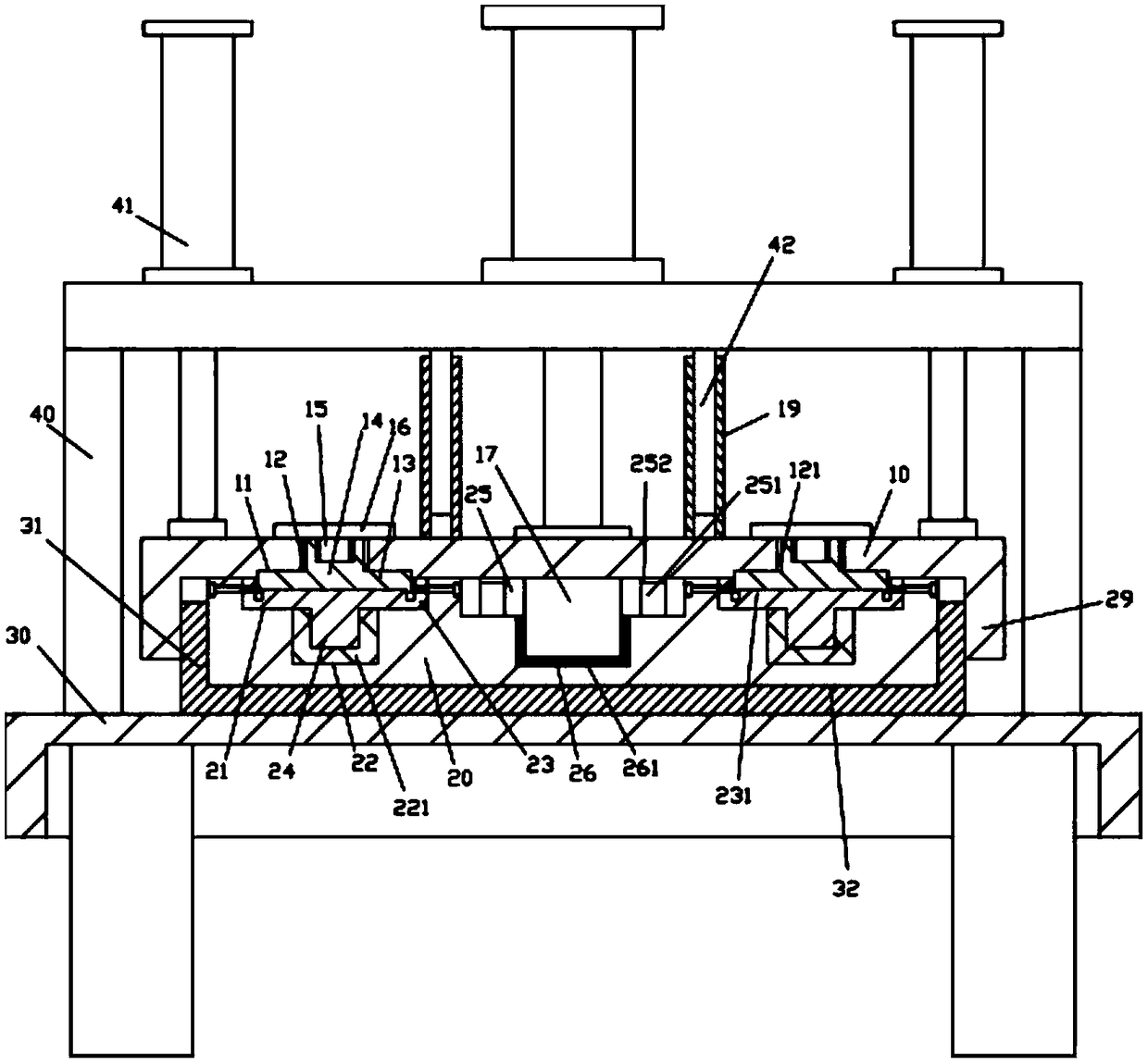
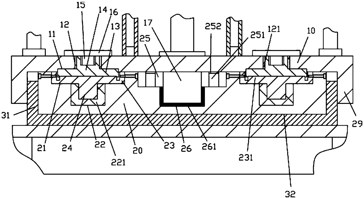
[0017] Examples, see e.g. Figure 1 to Figure 2 Shown, a kind of stamping mechanism that adopts multi-molding block mould, comprises frame 30, upper die mounting block 10 and lower die mounting block 20, the middle top surface of the top plate of described frame 30 is fixed with mounting block 31, and mounting block The middle part of the top surface of 31 has a lower installation groove 32, the lower mold installation block 20 is inserted in the lower installation groove 32 and fixedly connected to the bottom surface of the lower installation groove 32 by bolts, and the top surface of the top plate of the frame 30 is fixed with an upper support frame 40 , the top surface of the top plate of the upper support frame 40 is fixed with a plurality of stamping cylinders 41, and the push rods of all stamping cylinders 41 pass through the bottom surface of the top plate of the upper support frame 40 and are fixed on the top surface of the upper die mounting block 10;

[0018] The top...


PUM


Abstract

The invention discloses a punching mechanism adopting a die with multiple form blocks. The punching mechanism adopting the die with the multiple form blocks comprises a rack, an upper die installationblock and a lower die installation block, wherein an installation block is fixed to the top surface of the middle part of a top plate of the rack; a lower installation groove is formed in the middlepart of the top surface of the installation block; the lower die installation block is inserted and sleeved in the lower installation groove and is fixedly connected onto the bottom surface of the lower installation groove through a bolt; an upper support frame is fixed to the top surface of the top plate of the rack; multiple punching oil cylinders are fixed to the top surface of a top plate of the upper support frame; push rods of the punching oil cylinders penetrate through the bottom surface of the top plate of the upper support frame and are fixed onto the top surface of the upper die installation block; and two installation grooves are formed in the top surface of the lower die installation block. According to the punching mechanism provided by the invention, the multiple punching oil cylinders are adopted for punching, so that the forming stress is ensured to be uniform; meanwhile, multiple upper dies and lower dies are arranged on the upper die installation block and the lowerdie installation block, so that multiple products can be formed independently at one time; and when part of upper dies or lower dies are damaged, only the corresponding upper dies or lower dies need to be replaced.

Description

Technical field: [0001] The invention relates to the technical field of mold equipment, and more specifically relates to a stamping mechanism using a multi-block mold. Background technique: [0002] In the existing mold mechanism, it generally uses a single cylinder for stamping. For a large mold that molds multiple products at one time, the single cylinder stamping cannot achieve uniform force, and the effect is not ideal. In addition, the existing mold is generally directly on the upper mold. Multiple mold forming parts are set on the lower mold to realize multiple products forming at one time, and when part of the mold forming parts are damaged, the whole mold can only be replaced, and the replacement cost is high, and the repair and maintenance cost is high. Invention content: [0003] The purpose of the present invention is to overcome the deficiencies of the prior art and provide a stamping mechanism using multiple forming block molds. It uses multiple stamping cylin...

Claims


Application Information

Patent Timeline
Patent Type & Authority Applications(China)
IPC IPC(8): B30B1/34
CPCB30B1/34
Inventor 熊斌
Owner DONGGUAN TIANHE ELECTROMECHANICAL DEV CO LTD
Why Eureka
Try Eureka