Designing major hand-operated drawing board
A drawing board and hands-on technology, applied in painting tools, decorative arts, etc., can solve the problems of complicated adjustment and use, cumbersome operation, and troublesome
- Summary
- Abstract
- Description
- Claims
- Application Information
AI Technical Summary
Problems solved by technology
Method used
Image
Examples
Embodiment 1
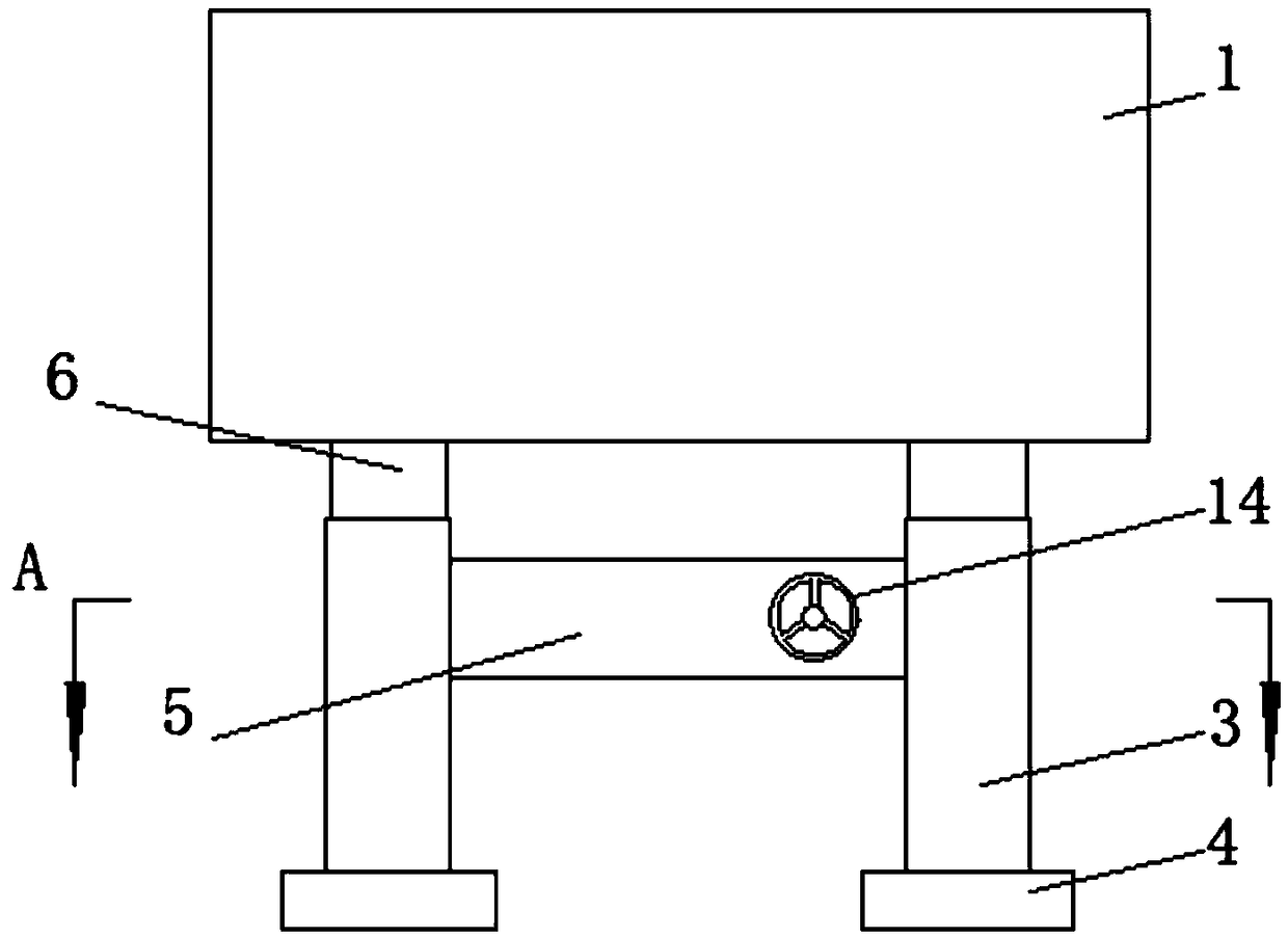
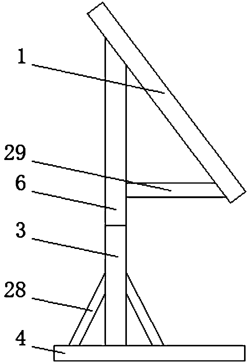
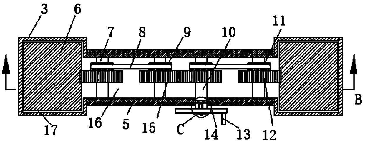
[0023] Embodiment 1, a hand-operated drawing board for professional design, including a drawing board 1, the upper end of the back of the drawing board 1 is provided with a symmetrically distributed first fixing frame 6, and the bottom of the first fixing frame 6 is provided with a second fixing frame 3. The second fixed frame 3 is provided with a telescopic slot 17, and the second fixed frame 3 is movably connected with the first fixed frame 6 through the telescopic slot 17, and the bottom of the back of the drawing board 1 is provided with a fixed rod 29, and the The fixed rod 29 is connected with the first fixed frame 6, and the connecting rod 5 fixedly connected is provided between the second fixed frame 3, and the adjusting groove 16 is arranged in the connecting rod 5, and the two ends of the adjusting groove 16 are respectively connected with the The telescopic groove 17 in the second fixed frame 3 is connected, and the middle part of the adjustment groove 16 is provided...
Embodiment 2
[0027] The same as embodiment 1 is no longer repeated, and the difference with embodiment 1 is:
[0028] Preferably, the inside of the first adjustment shaft 10 is provided with a first fixing groove 20, the first fixing groove 20 is provided with a fixing shaft 22, and the first adjustment shaft 10 is provided with a first fixing groove. 20 is perpendicular to the adjustment hole 27, and the adjustment hole 27 located at the two ends of the first fixing groove 20 is provided with a clamping rod 24, and the fixed shaft 22 on one side of the adjustment hole 27 is provided with a fixedly connected first hinge 23, so The two ends of the first hinge 23 are respectively provided with fixedly connected push rods 26, and the front ends of the push rods 26 are provided with a second hinge 25, and one end of the second hinge 25 is connected with the push rod 26, In addition, the other end of the second hinge 25 is connected to the clamping rod 24 , and the fixing hole 31 is provided wi...
Embodiment 3
[0031] The same as embodiment 1 is no longer repeated, and the difference with embodiment 1 is:
[0032] Preferably, the bottom of the second fixed frame 3 is provided with a support plate 4, and the two ends of the support plate 4 positioned at both ends of the second fixed frame 3 are provided with symmetrically distributed support rods 28, and one end of the support rod 28 is connected to the The second fixing bracket 3 is fixedly connected, and the other end of the support rod 28 is fixedly connected with the support plate 4 . A support plate is set at the bottom of the second fixed frame to make the second fixed frame more stable in use, and a support rod is set between the support plate and the second fixed frame, and the stability of the triangle is used to further improve the second fixed frame Stability during use.
PUM
 Abstract
Description
Claims
Application Information
 - R&D
- Intellectual Property
- Life Sciences
- Materials
- Tech Scout
- Unparalleled Data Quality
- Higher Quality Content
- 60% Fewer Hallucinations
Browse by: Latest US Patents, China's latest patents, Technical Efficacy Thesaurus, Application Domain, Technology Topic, Popular Technical Reports.
© 2025 PatSnap. All rights reserved.Legal|Privacy policy|Modern Slavery Act Transparency Statement|Sitemap|About US| Contact US: help@patsnap.com


