Binding rope
A technology for tying ropes and rope bodies, which is applied to bicycle accessories, luggage racks, and vehicles used for freight transportation, etc., can solve problems such as endangering the safety of bundling, and achieve the effects of not easy decoupling and easy adjustment.
- Summary
- Abstract
- Description
- Claims
- Application Information
AI Technical Summary
Problems solved by technology
Method used
Image
Examples
Embodiment 1
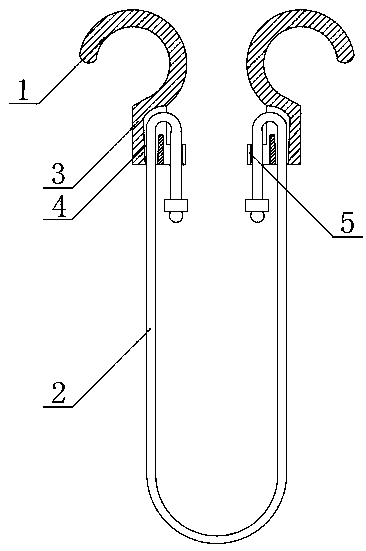
[0019] Embodiment 1: as figure 1 As shown, a binding rope includes a hook 1 and a rope body 2, the hook 1 is connected with a hook body 3, and the hook 1 and the hook body 3 are integrally molded.
[0020] A shaft hole 4 is provided through the hook body 3 to allow the rope body 2 to pass through, and the axial inner diameter of the shaft hole 4 gradually decreases from one end to the other end.
[0021] On the side wall of the hook body 3, there is a tiger's mouth clip 5 protruding outwards. The tiger's mouth clip 5 and the shaft hole 5 are misplaced and arranged inconcentrically. More specifically, the tiger's mouth clip and the shaft hole are arranged side by side, so that after the rope body passes through the shaft hole Fold it back and buckle it into the tiger's mouth clip to form a fold with the largest angle, which is the most stable.
[0022] Use 1: Put the rope body through the shaft hole, select the appropriate position of the hook body on the rope body, and then t...
Embodiment 2
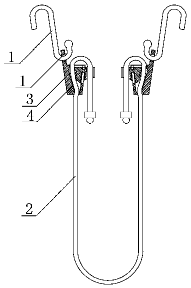
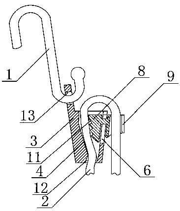
[0023] Embodiment 2: as figure 2 , image 3 and Figure 4 As shown, a binding rope includes a hook 1 and a rope body 2, the hook 1 is connected with a hook body 3, the hook body 3 is provided with a hanging nose 13, and the hook 1 is movably arranged on the hanging nose 13.
[0024] A shaft hole 4 is provided through the hook body 3 to allow the rope body 2 to pass through, and the axial inner diameter of the shaft hole 4 gradually decreases from one end to the other end. The shaft hole 4 is formed with a bend outlet 12 at the outlet of the smaller end of the aperture. Let the rope body make a turn in the shaft hole, and the direction of the force is changed so that the rope body is not easy to slide.
[0025] A chute 6 is arranged on the side wall of the hook body 3. The opening of the chute 6 is on the edge of the opening with a large inner diameter of the shaft hole 4. A sliding block 7 is fitted on the chute 6. The opening of the chute 6 is provided with a pair of limi...
PUM
 Abstract
Description
Claims
Application Information
 - R&D
- Intellectual Property
- Life Sciences
- Materials
- Tech Scout
- Unparalleled Data Quality
- Higher Quality Content
- 60% Fewer Hallucinations
Browse by: Latest US Patents, China's latest patents, Technical Efficacy Thesaurus, Application Domain, Technology Topic, Popular Technical Reports.
© 2025 PatSnap. All rights reserved.Legal|Privacy policy|Modern Slavery Act Transparency Statement|Sitemap|About US| Contact US: help@patsnap.com


