A hydraulically driven filter automatic cutting machine

A filter element, automatic technology, applied in the direction of metal processing, etc., can solve the problems of damage and repair times, large pressure on the motor guide rail, unstable swinging large bracket, etc., to achieve the effect of convenient installation and operation, and cost control.

Active Publication Date: 2016-09-28
ANHUI HONGSHI ENVIRONMENTAL TECH
View PDF8 Cites 0 Cited by
  • Summary
  • Abstract
  • Description
  • Claims
  • Application Information

AI Technical Summary

Problems solved by technology

[0005]1. Requires multiple receiver shafts and creates a lot of waste when replaced
[0006]2. The replaced receiving shaft needs to be manually removed and cut manually
[0007]3. Due to the limitation of reciprocating motion, the filter elements at both ends will be scrapped, and the yield rate is only about 70%
[0010]1. When cutting, one motor drives the screw to move laterally while the other motor drives the blade to rotate and cut the filter element. Cuts are left, and the section of the filter element does not meet the requirements
[0011]2. Due to the installation of two motor guide rails, it is difficult to slide due to the large pressure, and the swing is large and the bracket is unstable
Easy to cause damage and more frequent repairs
[0012]3. The cutting length of the filter element is short, and the longer filter element needs to be cut manually

Method used


Image

  • A hydraulically driven filter automatic cutting machine

Examples


Embodiment Construction

[0022] Below in conjunction with accompanying drawing, the present invention is described in further detail by embodiment:

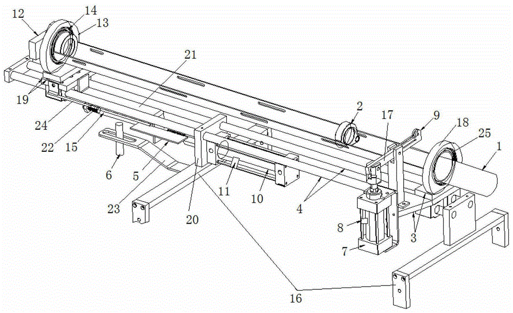
[0023] A hydraulically driven filter automatic cutting machine, including a base 16 and a slide rail 4: a pair of slide rails 4 are installed on the upper end of the base 16, a front bracket 3 is slidingly installed on the front end of the slide rail 4, and a cutter cylinder is fixedly installed on the side of the front bracket 3 7, the piston end of the cutter cylinder 7 is connected with an extension rod 17, the front end of the extension rod 17 is equipped with a cutter head 9, the cutter cylinder 7 side is equipped with a cutter cylinder electromagnetic sensor 8, and the cutter cylinder 7 is equipped with a The electromagnetic ring matched by the cutter cylinder electromagnetic sensor 8; the front bracket 3 upper end is equipped with a front receiving groove fixed runner 18, and the front receiving groove fixed runner is clamped with a front bearing 2...


PUM


Abstract

The invention discloses a hydraulically-driven automatic filter element cutter which comprises a base and slide tracks, wherein a pair of slide tracks is mounted at the upper end of the base; front brackets are mounted at the front ends of the slide tracks; a cutter air cylinder is fixedly mounted on the side edges of the front brackets; the piston end of the cutter air cylinder is connected with an extension rod of which the front end is equipped with a cutter head; a front receiving groove fixing runner is mounted at the upper ends of the front brackets; rear brackets are mounted at the rear ends of the slide tracks in a sliding manner; a rear receiving groove fixing runner is mounted at the upper ends of the rear brackets; a runner is mounted in a filter element receiving groove which penetrates the front and rear receiving groove fixing runners; a rotating cylinder is arranged at the position above the rear end of the base and is connected to the end part of the filter element receiving groove; a fixing plate is arranged in the middle of the base and is provided with a hydraulic ram at the side edge; an extended connecting rod is fixed at the rear end of the base, and a top plate is fixedly mounted at the front ends of the rear brackets and is sleeved on the connecting rod; and the piston end of the hydraulic ram is propped against the top plate. Based on the automatic cutter home and abroad, through continual trial and innovation, with the adjustability of a pneumatic element, the difficult problems that the cutter is fed slowly and withdrawn quickly are solved, and the end surfaces of the cut filter element are flat and smooth, which meets the requirements of customers.

Description

technical field [0001] The invention relates to the field of filter element production equipment, in particular to a hydraulically driven filter element automatic cutting machine. Background technique [0002] The filter element is a polymer (PP polypropylene) extruded from the spinneret hole in the melt-blown state, and is subjected to the action of high-speed hot air to make it into ultra-fine fibers and pass through the pore-shaped water filter produced by the unequal speed transmission of the receiving shaft. Consumables. At present, with the popularization and use of various domestic water purification equipment, the consumption of filter elements is also increasing rapidly. [0003] According to the usual customer requirements, the outer surface of the filter element is required to be smooth and the outer diameter is required to be within the standard tolerance range, and the two sections are required to be flat and smooth. The length requires plus or minus 1mm. [0...

Claims


Application Information

Patent Timeline
Patent Type & Authority Patents(China)
IPC IPC(8): B26D1/30B26D5/00B26D5/12B26D7/26B26D7/06
Inventor 黄春节徐家茂
Owner ANHUI HONGSHI ENVIRONMENTAL TECH
Why Eureka
Try Eureka