Optical fiber hoisting and laying device

A technology for laying devices and optical fibers, applied in the field of information communication, can solve the problems of laborious construction and laying, low laying efficiency, time-consuming and labor-consuming, etc., and achieve the effects of improving efficiency, avoiding random falling, and being convenient for hoisting and fixing.

Active Publication Date: 2018-12-18
重庆知行知识产权服务有限公司
View PDF20 Cites 16 Cited by
  • Summary
  • Abstract
  • Description
  • Claims
  • Application Information

AI Technical Summary

Problems solved by technology

[0002] Communication is in the process of human practice. With the development of social productivity, the requirements for message transmission are constantly improving, which makes human civilization continue to progress. With the integration of industrialization and informationization, and the continuous increase in government public security investment, the private network communication market The scale has been expanding in recent years, and the requirements for the construction of basic communication facilities are getting higher and higher. The traditional optical fiber laying mainly relies on manual laying. The optical cable wound by the optical cable is pulled out manually, and the hoisting steel wire and the The utility pole is fixed, and then the optical cable and the hoisting steel wire are hoisted and fixed through the hook. During the construction process, it is very laborious to pull the optical cable and the optical cable needs to be pulled to the height of the utility pole. The construction and laying is very laborious and requires a lot of time and manpower. The laying efficiency low

Method used


Image

  • Optical fiber hoisting and laying device
  • Optical fiber hoisting and laying device
  • Optical fiber hoisting and laying device

Examples


Embodiment Construction

[0018] The following will clearly and completely describe the technical solutions in the embodiments of the present invention with reference to the accompanying drawings in the embodiments of the present invention. Obviously, the described embodiments are only some, not all, embodiments of the present invention. Based on the embodiments of the present invention, all other embodiments obtained by persons of ordinary skill in the art without making creative efforts belong to the protection scope of the present invention.

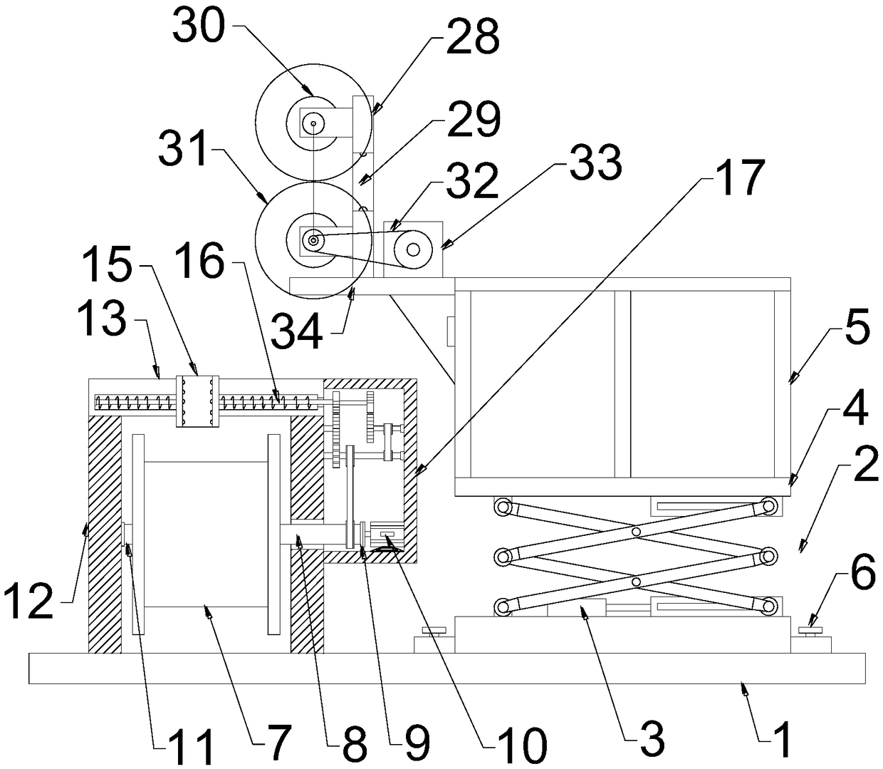
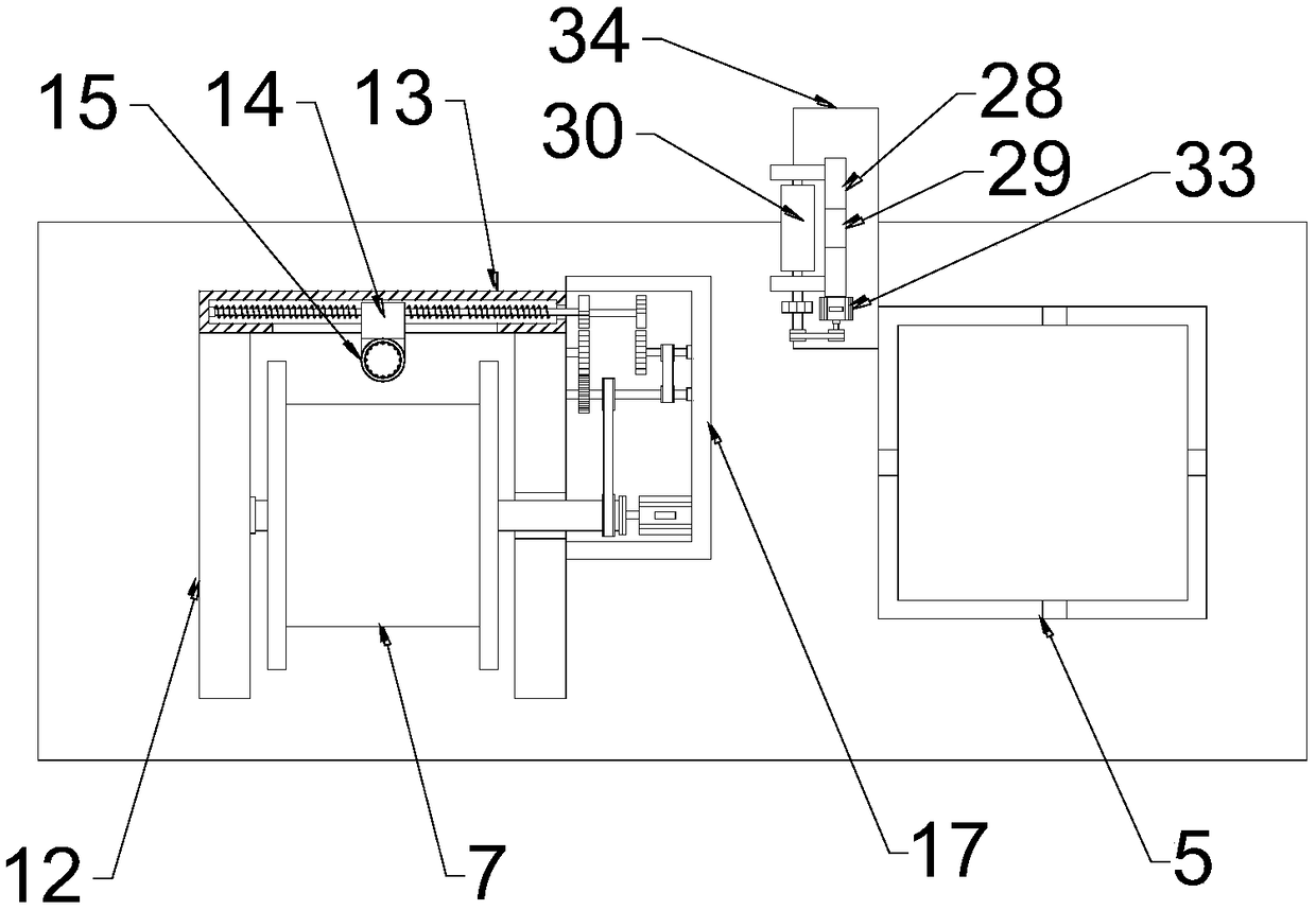
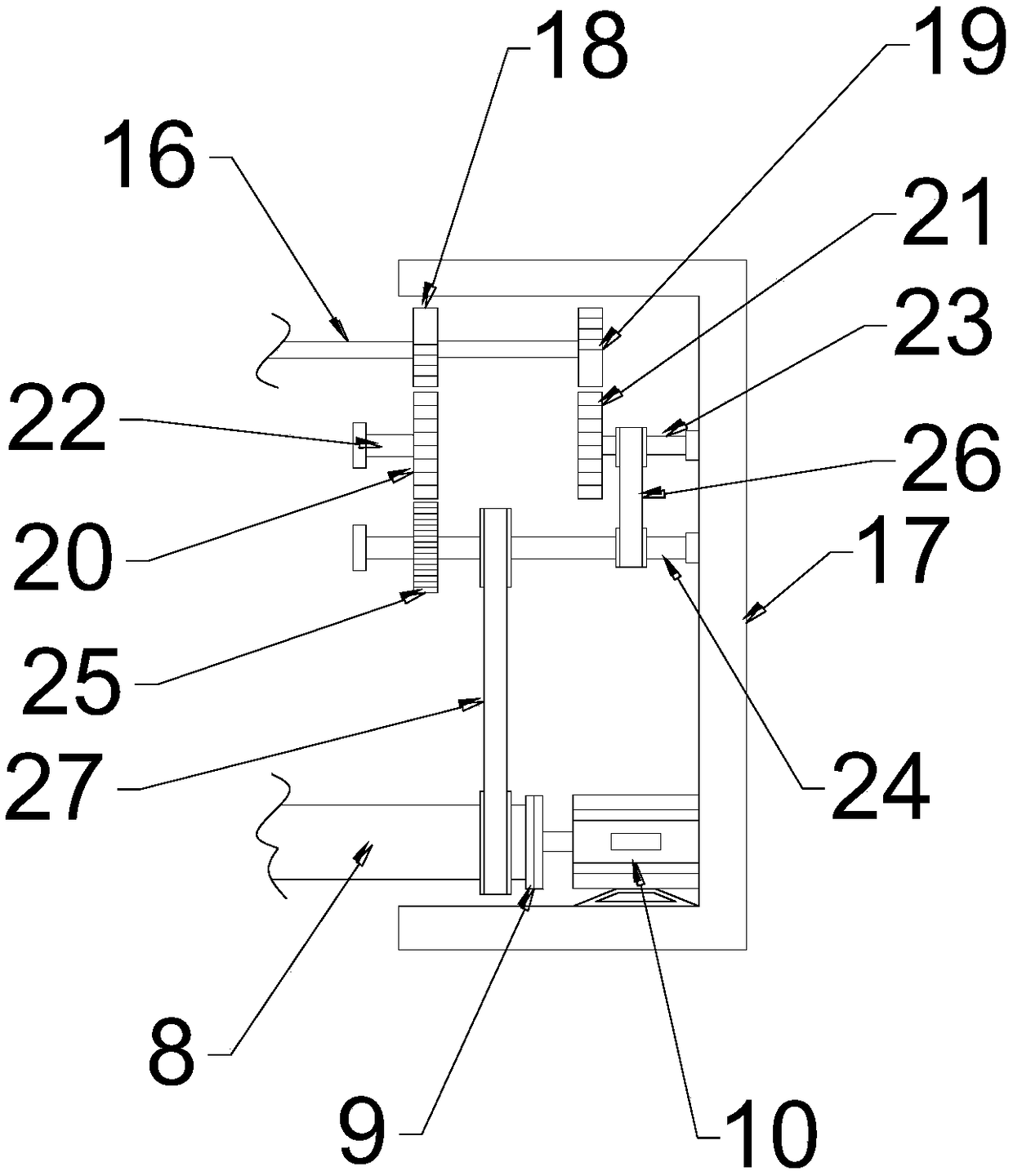
[0019] see Figure 1~3 , in an embodiment of the present invention, an optical fiber hoisting and laying device includes a tooling base 1, a scissor lift table 2, a laying and rolling mechanism, and a traction mechanism; the tooling base 1 is fixed by being connected to an external truck floor, and then drives The device moves for hoisting and laying; the right side of the tooling base 1 is provided with a scissor lift platform 2, and the scissor lift platform...


PUM


Abstract

The invention discloses an optical fiber hoisting and laying device. The optical fiber hoisting and laying device comprises a tool base, a scissor fork type lifting table, a laying winding mechanism and a traction mechanism, the scissor fork type lifting table is arranged on the right side of the tool base, the laying winding mechanism is arranged on the left side of the scissor fork type liftingtable, the traction mechanism is arranged on the left side of a guardrail, the traction mechanism comprises a guide plate, the guide plate is vertically arranged, and a mounting plate is perpendicularly and fixedly connected with the bottom of the guide plate. According to the optical fiber hoisting and laying device, a guide ring and a gear transmission mechanism are arranged, so that when the optical cable is released by an optical fiber winding roll, the guide ring moves synchronously and transversely in a reciprocating mode, then the traction resistance of the optical cable is smaller, theoptical cable can be prevented from falling off at will, and the optical cable is protected; and traction rollers rotating oppositely are arranged, so that the optical cable is pulled to a high position, the optical cable is pulled to the high position in a labor-saving mode, hoisting and fixing are facilitated, compared with manual traction, the optical fiber hoisting and laying device is labor-saving and efficient, the optical fiber hoisting and laying device is driven by an external truck to move, efficient hoisting and laying are carried out, so that the hoisting and laying efficiency ofthe optical cable is remarkably improved.

Description

technical field [0001] The invention relates to the field of information communication, in particular to an optical fiber hoisting and laying device. Background technique [0002] Communication is in the process of human practice. With the development of social productivity, the requirements for message transmission are constantly improving, which makes human civilization continue to progress. With the integration of industrialization and informationization, and the continuous increase in government public security investment, the private network communication market The scale has been expanding in recent years, and the requirements for the construction of basic communication facilities are getting higher and higher. The traditional optical fiber laying mainly relies on manual laying. The optical cable wound by the optical cable is pulled out manually, and the hoisting steel wire and the The utility pole is fixed, and then the optical cable and the hoisting steel wire are ho...

Claims


Application Information

Patent Timeline
Patent Type & Authority Applications(China)
IPC IPC(8): B65H49/34B65H49/30B65H51/10G02B6/48
CPCB65H49/30B65H49/34B65H51/10B65H2701/32G02B6/48
Inventor 刘会
Owner 重庆知行知识产权服务有限公司
Why Eureka
Try Eureka