Pump head device

A pump head and kit technology, which is applied to pump devices, parts of pumping devices for elastic fluids, pumps, etc., can solve the problem of high maintenance costs of pump head devices, and achieve the effect of reducing maintenance costs

Inactive Publication Date: 2018-12-18
WUHAN MARINE MACHINERY PLANT
View PDF4 Cites 1 Cited by
  • Summary
  • Abstract
  • Description
  • Claims
  • Application Information

AI Technical Summary

Problems solved by technology

However, since the balance device is fixed on the impeller, the balance device must rotate together with the impeller. Once the balance device wears out, the entire impeller needs to be replaced together, resulting in high maintenance costs for the pump head device.

Method used


Image

  • Pump head device
  • Pump head device
  • Pump head device

Examples


Embodiment Construction

[0024] In order to make the object, technical solution and advantages of the present invention clearer, the implementation manner of the present invention will be further described in detail below in conjunction with the accompanying drawings.

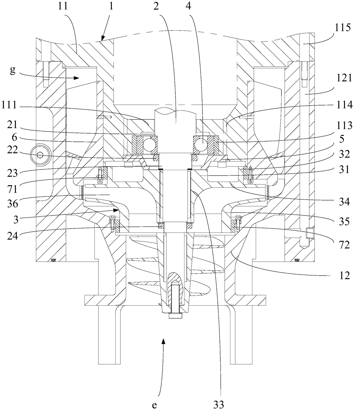
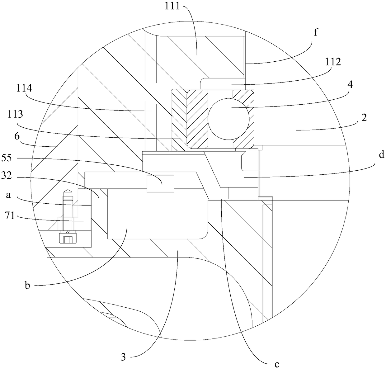
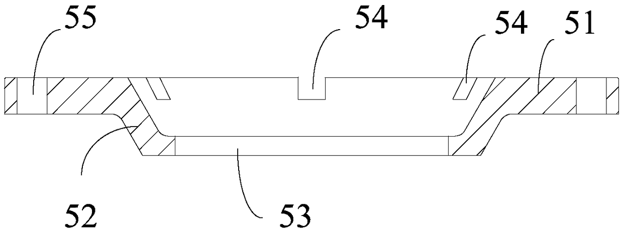
[0025] The embodiment of the present invention provides a pump head device, such as figure 1 As shown, the pump head device is suitable for cryogenic submersible pumps. The pump head device includes: a housing 1, a main shaft 2, an impeller 3 and a bearing 4. The main shaft 2 is rotatably inserted in the housing 1, and the impeller 3 is coaxial The fixed sleeve is mounted on the main shaft 2, and the bearing 4 and the bearing are sleeved on the main shaft 2. The outer wall of the bearing 4 is clamped with the inner wall of the housing 1. The top middle of the impeller 3 is coaxially provided with a boss 31, and the outer top of the impeller 3 The edge is coaxially provided with a sealing ring 32, and a first flow gap a is provided betw...


PUM


Abstract

The invention discloses a pump head device, and belongs to the field of immersed pumps. The pump head device comprises a shell body, a main shaft, an impeller and a bearing, wherein a boss is coaxially arranged at the middle part of the top of the impeller; a sealing ring is coaxially arranged on the outer edge of the top of the impeller; and a first overflow gap is formed between the outer wall of the sealing ring and the inner wall of the shell body. The pump head device further comprises a balance disc, wherein the balance disc sleeves the main shaft; the balance disc comprises a first flange ring, a connection cone and a second flange ring; the first flange ring is detachably installed on the inner wall of the shell body, a first overflow cavity is formed among the sealing ring, the impeller, the boss, the balance disc and the shell body; a second overflow gap is formed between the second flange ring and the boss; a second overflow cavity is formed among the connection cone, the second flange ring and the main shaft; and a low-pressure inlet of the shell body, the first overflow gap, the first overflow cavity, the second overflow gap, the second overflow cavity, and a gap between an inner ring and an outer ring of the bearing are sequentially communicated. The maintenance cost for the pump head device is lowered.

Description

technical field [0001] The invention belongs to the field of submersible pumps, in particular to a pump head device. Background technique [0002] A submersible pump is a common type of centrifugal pump that is usually installed in ships to pump cryogenic liquefied gases. [0003] The pump head device is an important part of the submersible pump. It mainly includes a housing, a main shaft and an impeller. The main shaft is rotatably inserted in the housing. , the impeller rotates with the main shaft to realize the pumping of liquid cargo. [0004] In order to balance the upward axial force of the impeller caused by the uneven force on the upper and lower cover plates of the impeller when the submersible pump is working, a balance device is usually fixed on the upper cover plate of the impeller. The change of the flow gap between the balance device and the inner wall of the casing is used to enable the impeller to receive a downward axial force, so as to realize the balance...

Claims


Application Information

Patent Timeline
Patent Type & Authority Applications(China)
IPC IPC(8): F04D13/08F04D29/06F04D29/041F04D29/62
CPCF04D13/08F04D29/041F04D29/061F04D29/628
Inventor 张聪杨勤甘正林田永珍
Owner WUHAN MARINE MACHINERY PLANT
Why Eureka
Try Eureka