Industrial rail parallelism detection robot

A technology of parallelism and robotics, applied in the direction of instruments, measuring devices, optical devices, etc., can solve problems such as installation troubles, robot disassembly troubles, inconvenient maintenance and replacement parts, etc., to achieve simple installation work, clear test results, Ease of use

Active Publication Date: 2018-12-18
泰州帕沃能源科技有限公司
View PDF8 Cites 4 Cited by
  • Summary
  • Abstract
  • Description
  • Claims
  • Application Information

AI Technical Summary

Problems solved by technology

[0003] Aiming at the deficiencies of the prior art, the present invention provides an industrial track parallelism detection robot, which has the advantages of being able to quickly disassemble the robot, making it convenient for staff to maintain the robot, and solves most of the problems of the existing track parallelism detection robots. One-piece structure, so when the robot fails, it is more troublesome to disassemble the robot, it is inconvenient to repair and replace parts, and it is more troublesome to install after the repair is completed

Method used


Image

  • Industrial rail parallelism detection robot
  • Industrial rail parallelism detection robot
  • Industrial rail parallelism detection robot

Examples


Embodiment 1

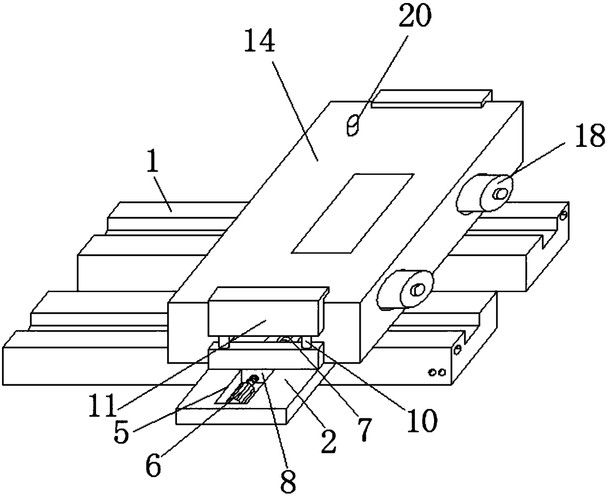
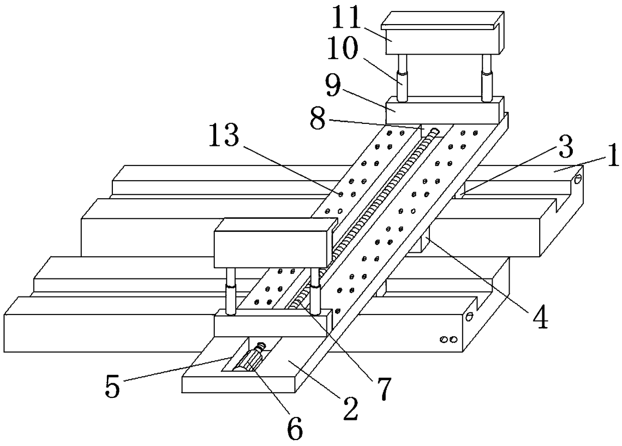
[0022] see Figure 1-4 , the present embodiment provides an industrial track parallelism detection robot, comprising two track bodies 1 and a positioning plate 2, the bottom of the positioning plate 2 is fixedly connected with a hinged seat 19, and the hinged seat 19 The bottom is hinged with a detection slider 3, the detection slider 3 is slidingly connected with the track body 1, the bottom of the positioning plate 2 is fixedly installed with a driving wheel assembly 4, the driving wheel assembly 4 is movably connected with the track body 1, and the top of the positioning plate 2 is opened There is a chute 5, the inner wall of the chute 5 is fixedly connected with a motor 6, the output shaft of the motor 6 is fixedly connected with a screw rod 7, the surface of the screw rod 7 is threadedly connected with a screw rod sliding sleeve 8, and the top of the screw rod sliding sleeve 8 is fixed Connected with a moving plate 9, the top of the moving plate 9 is fixedly connected wit...

Embodiment 2

[0025] see Figure 1-4 , on the basis of Example 1, a further improvement has been made: there is a gap between the bottom of the positioning plate 2 and the track body 1, and the positioning plate 2 is not in contact with the track body 1, which can effectively prevent the stains on the track body 1 from affecting the measurement results As a result, the drive wheel assembly 4 includes an asynchronous motor and a drive wheel, the asynchronous motor and the drive wheel are connected in rotation, and the power supply is controlled by the control assembly 17, so that the asynchronous motor drives the drive wheel to rotate, so that the robot can move by itself, and the positioning plate The top of 2 is provided with evenly distributed heat dissipation holes 13 to avoid excessive heat generation at the contact with the positioning plate 2 when the robot is working.

[0026] Wherein, the inner wall of the chute 5 is fixedly connected with a rotating seat 12, and the inner wall of t...

Embodiment 3

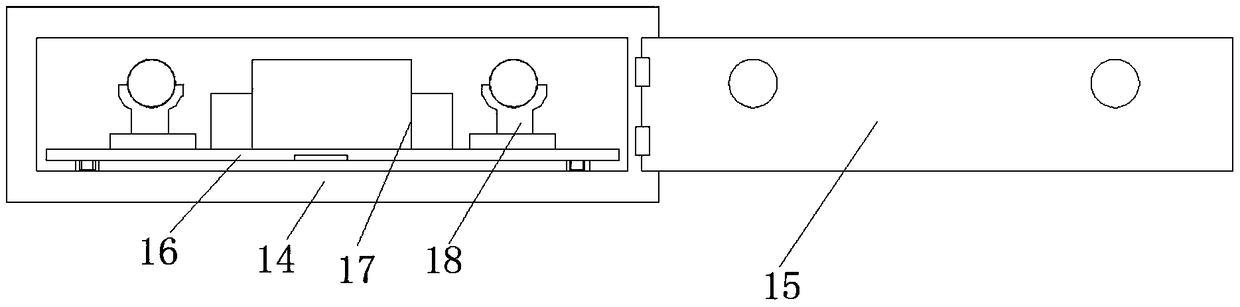
[0028] see figure 1 Or 3, a further improvement is made on the basis of Embodiment 1: the control assembly 17 includes a battery and a central controller, and when the parallelism is detected, the battery is used to supply power to the device, and the central controller plays a role in controlling the entire motion process , the top of the casing 14 is fixedly connected to the limit guide rail, the inner wall of the limit guide rail is slidably connected with a slider, the slider is fixedly connected to the mounting plate 16, and the sliding block slides inside the limit guide rail, so that the pulling of the mounting plate 16 can be made more efficient. Smooth, and can play a position-limiting effect on the mounting plate 16, preventing it from tilting or shifting.


PUM


Abstract

The invention relates to the technical field of an industrial robot and discloses an industrial rail parallelism detection robot. The industrial rail parallelism detection robot comprises two rail bodies and a positioning plate. Detection slide blocks are fixedly connected with the bottom of the positioning plate. The detection slide blocks are in slide connection with the rail bodies. Drive wheelassemblies are fixedly mounted at the bottom of the positioning plate. The drive wheel assemblies are movably connected with the rail bodies. A slide slot is set on the top of the positioning plate.A motor is fixedly connected with the inner wall of the slide slot. A screw rod is fixedly connected with an output shaft of the motor. Screw rod slide bushings are in threaded connection with the surface of the screw rod. Moving plates are fixedly connected with the tops of the screw rod slide bushings. According to the industrial rail parallelism detection robot, the problem that most of the existing rail parallelism detection robots are integrated structures, when faults occur in the robots, the robots are relatively troublesome to disassemble, maintenance or replacement of parts is inconvenient, and after the maintenance is finished, assembly is relatively troublesome is solved.

Description

technical field [0001] The invention relates to the technical field of industrial robots, in particular to an industrial track parallelism detection robot. Background technique [0002] In the process of industrial production, robots are widely used. Among them, in the process of parallelism detection of industrial tracks, parallelism detection robots are the longest used type of track detection. Most of the existing industrial track parallelism detection robots are integrated. structure, so when the robot breaks down, it is cumbersome to disassemble the robot, it is inconvenient to repair and replace parts, and it is cumbersome to install after the repair is completed, which is inconvenient for users to use. Contents of the invention [0003] Aiming at the deficiencies of the prior art, the present invention provides an industrial track parallelism detection robot, which has the advantages of being able to quickly disassemble the robot, making it convenient for staff to m...

Claims


Application Information

Patent Timeline
Patent Type & Authority Applications(China)
IPC IPC(8): G01B11/26
CPCG01B11/26
Inventor 吴瑞
Owner 泰州帕沃能源科技有限公司
Why Eureka
Try Eureka