
Display driving method, display driving device and display equipment

A technology for display driving and pre-display, which is applied in the fields of display equipment, display driving methods, and display driving devices, and can solve problems such as flickering of display screens, different voltages, aggravated flickering and afterimages of display screens, etc., and achieves simplified test steps, flickering, etc. When the value is small, the effect of reducing screen flicker and afterimage phenomenon

Inactive Publication Date: 2018-12-18
XIAMEN TIANMA MICRO ELECTRONICS
View PDF15 Cites 2 Cited by
  • Summary
  • Abstract
  • Description
  • Claims
  • Application Information

AI Technical Summary

Problems solved by technology

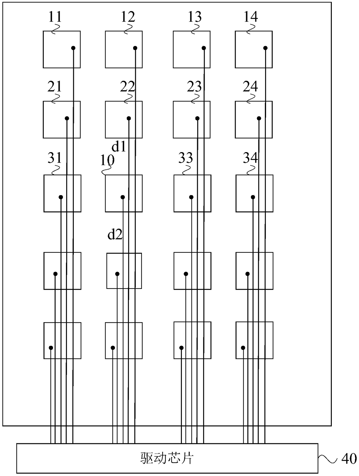
[0004] However, due to the different distances between different common electrode blocks and the driving chip in the actual display device, the lengths of the metal wires connected between each common electrode block and the driving chip are different, resulting in different resistances of the metal wires.
When the drive chip outputs the same voltage to each common electrode block, the actual voltage received by each common electrode block is different, and finally the driving voltage difference between the pixel electrode and the common electrode is different when the display device is in a positive frame and a negative frame at different positions. Equal, resulting in flickering and afterimage problems on the display screen
Moreover, since the output voltage of the driver chip is the best common voltage corresponding to a certain gray scale, when the display screen displays other gray scales, the common voltage is not optimal, which further aggravates the problems of flickering and afterimages on the display screen

Method used


Image

  • Display driving method, display driving device and display equipment
  • Display driving method, display driving device and display equipment
  • Display driving method, display driving device and display equipment

Examples


Embodiment Construction

[0025] The present invention will be further described in detail below in conjunction with the accompanying drawings and embodiments. It should be understood that the specific embodiments described here are only used to explain the present invention, but not to limit the present invention. In addition, it should be noted that, for the convenience of description, only some structures related to the present invention are shown in the drawings but not all structures.

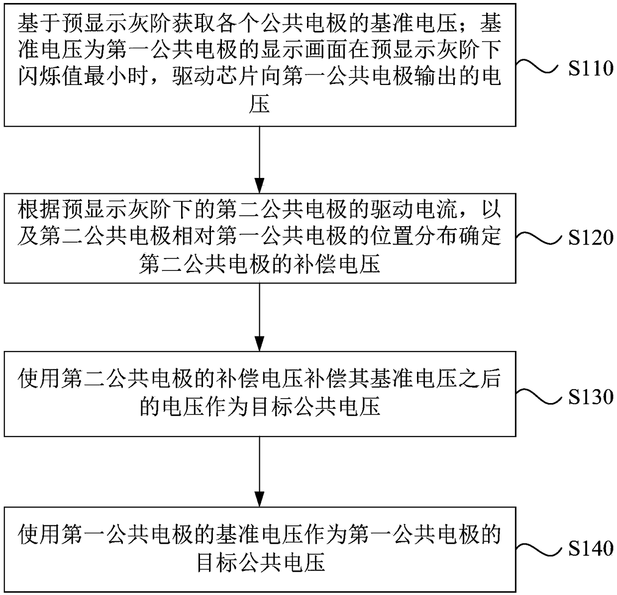
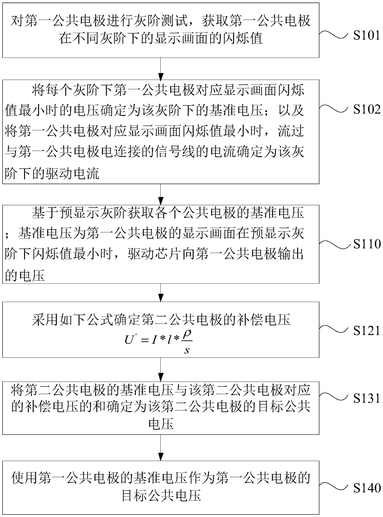
[0026] figure 1 is a flow chart of a display driving method provided by an embodiment of the present invention, figure 2 is a schematic structural diagram of a display panel provided by an embodiment of the present invention, refer to figure 1 with figure 2 , the display driving method is used to drive a display panel, the display panel includes a plurality of common electrodes and a plurality of pixel electrodes (not shown in the figure), and the common electrodes include a first common electrode 10 and a fir...


PUM


Abstract

The invention discloses a display driving method, a display driving device and display equipment; the display driving method comprises the following steps: obtaining a reference voltage of each commonelectrode according to a pre-display gray scale, wherein the reference voltage is the voltage outputted by a driving chip to the first common electrode when the scintillation value of the display frame of the first common electrode is minimum under the pre-display gray scale; determining a compensation voltage of the second common electrode according to a driving current of the second common electrode under the pre-display gray scale and the position of the second common electrode with respect to the first common electrode; using the second common electrode compensation voltage to compensatethe reference voltage, and using the obtained voltage as the target common voltage; using the reference voltage of the first common electrode as the target common voltage of the first common electrode. The method and device can adjust the output voltage of the driving chip according to the gray scale of to-be-displayed frame of each common electrode and the position of each common electrode, thusreducing the display frame scintillation and Mura phenomenon.

Description

technical field [0001] Embodiments of the present invention relate to the field of display technologies, and in particular, to a display driving method, a display driving device, and a display device. Background technique [0002] With the development of display technology, people have higher and higher requirements for the quality of the images displayed by the display device. [0003] The vehicle-mounted display device in the prior art usually includes a display area and a non-display area. The display area is provided with pixel electrodes and a plurality of common electrode blocks, and the driver chip disposed in the non-display area is connected to each common electrode block through metal wires. In the display stage, the driving chip outputs the same voltage to multiple common electrode blocks through metal wires, and the voltage corresponds to an optimal common voltage for a certain gray scale value. For the ideal driving voltage, in the case of positive frame and ne...

Claims


Application Information

Patent Timeline
Patent Type & Authority Applications(China)
IPC IPC(8): G09G3/20
CPCG09G3/20G09G2320/0271
Inventor 吴玲郑斌义沈柏平
Owner XIAMEN TIANMA MICRO ELECTRONICS
Learn More