
Pixel circuit, pixel driving method and display device

A pixel circuit and circuit technology, applied in static indicators, instruments, etc., can solve the problem of uneven brightness of light-emitting elements, and achieve the effect of improving display unevenness.

Active Publication Date: 2021-04-09
BOE TECH GRP CO LTD
View PDF5 Cites 0 Cited by
  • Summary
  • Abstract
  • Description
  • Claims
  • Application Information

AI Technical Summary

Problems solved by technology

[0003] The main purpose of the present invention is to provide a pixel circuit, a pixel driving method and a display device to solve the problem of uneven luminance of light-emitting elements in the existing display devices

Method used


Image

  • Pixel circuit, pixel driving method and display device
  • Pixel circuit, pixel driving method and display device
  • Pixel circuit, pixel driving method and display device

Examples


Embodiment Construction

[0054] The following will clearly and completely describe the technical solutions in the embodiments of the present invention with reference to the accompanying drawings in the embodiments of the present invention. Obviously, the described embodiments are only some, not all, embodiments of the present invention. Based on the embodiments of the present invention, all other embodiments obtained by persons of ordinary skill in the art without making creative efforts belong to the protection scope of the present invention.

[0055] The transistors used in all the embodiments of the present invention can be thin film transistors or field effect transistors or other devices with the same characteristics. In the embodiment of the present invention, in order to distinguish the two poles of the transistor except the control pole, one pole is called the first pole, and the other pole is called the second pole. In actual operation, the control electrode may be a gate, the first electrode...


PUM


Abstract

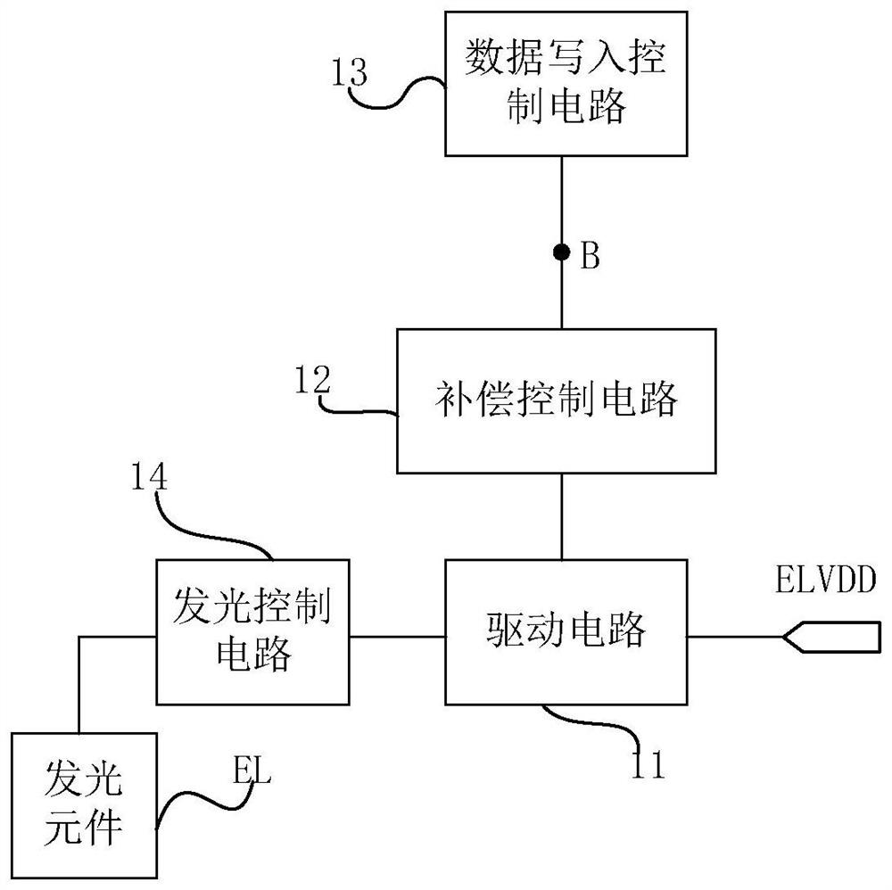
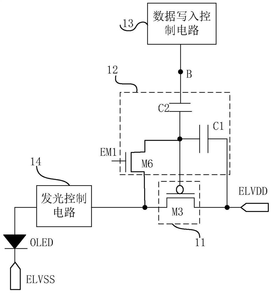
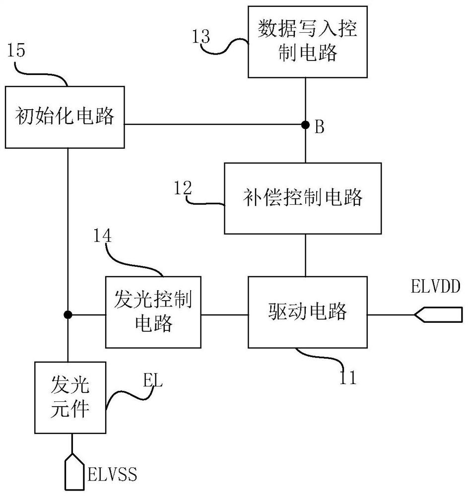
The invention provides a pixel circuit, a pixel driving method and a display device. The pixel circuit includes a light-emitting element, a driving circuit, a compensation control circuit, a data writing control circuit, and a lighting control circuit, wherein the data writing control circuit is configured to control writing of data voltages into the compensation during the data writing phase. a control circuit; the compensation control circuit is configured to control and compensate the potential of the control terminal of the driving circuit in the compensation phase, and control and adjust the potential of the control terminal of the driving circuit according to the data voltage control in the data writing phase; the The light emission control circuit is configured to control the connection state between the driving circuit and the light emitting element during the light emission phase. The present invention improves display unevenness.

Description

technical field [0001] The present invention relates to the field of display technology, in particular to a pixel circuit, a pixel driving method and a display device. Background technique [0002] In the existing pixel circuit, under the control of the light emission control signal, the power supply voltage ELVDD is input. Since the power supply voltage lines of the input power supply voltage ELVDD are arranged in a row, as the transmission between the pixel circuit and the power supply voltage lines As the distance becomes larger, the voltage value of the power supply voltage input to the far-end pixel circuit is smaller than the voltage value of the power supply voltage input to the near-end, while the luminous brightness of the light-emitting element in the existing pixel circuit is related to ELVDD, thus displaying in the light-emitting stage There will be uneven display at the near and far ends of the screen. Contents of the invention [0003] The main purpose of th...

Claims


Application Information

Patent Timeline
Patent Type & Authority Patents(China)
IPC IPC(8): G09G3/3208
CPCG09G3/3208
Inventor 高雪岭
Owner BOE TECH GRP CO LTD
Learn More