
A Z-shaped wire stranding device and a wire stranding machine

A technology of stranding and guiding devices, applied in the field of stranding machines, can solve problems such as inability to twist external wires

Pending Publication Date: 2018-12-18
JIANGSU HENGTONG ELECTRICAL SPECIAL WIRE CO LTD
View PDF8 Cites 3 Cited by
  • Summary
  • Abstract
  • Description
  • Claims
  • Application Information

AI Technical Summary

Problems solved by technology

[0003] The twisting machine includes a plurality of Z-shaped wire twisting devices, and the function of the Z-shaped wire twisting device is to wind a plurality of outer conductors on the outside of the central conductor. The stranded wires of the outer conductors are stranded, and the outer conductors with a Z-shaped cross section cannot be stranded

Method used


Image

  • A Z-shaped wire stranding device and a wire stranding machine
  • A Z-shaped wire stranding device and a wire stranding machine
  • A Z-shaped wire stranding device and a wire stranding machine

Examples


Embodiment 1

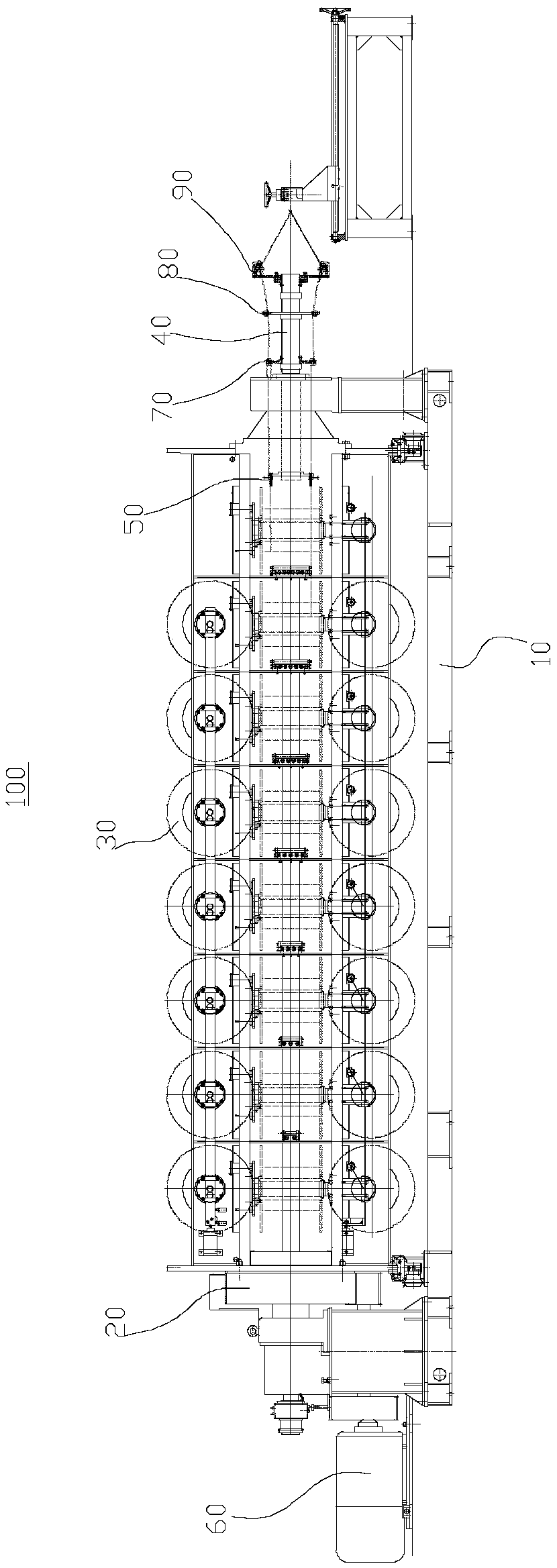
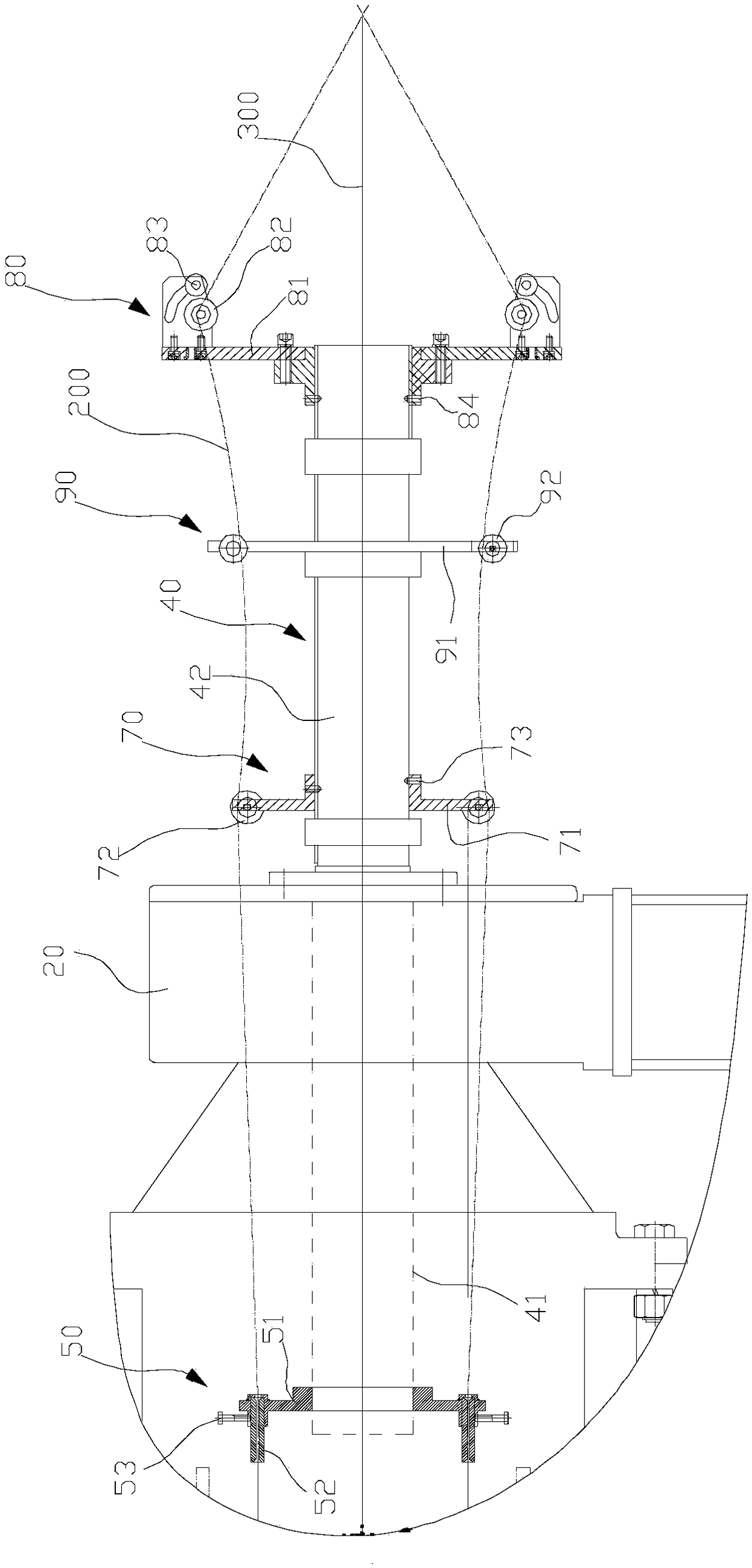
[0053] Such as figure 1 As shown, the present embodiment provides a Z-shaped wire stranding device 100 , including a frame body 10 , a strand body 20 , a plurality of winding wheels 30 , a central tube 40 and a positioning device 50 . The twisted body 20 is rotatably arranged on the frame body 10; the winding wheel 30 is rotatably arranged on the twisted body 20, and the winding wheel 30 is used for winding the outer wire 200 whose cross section is Z-shaped; the central tube 40 is fixed on the twisted body 20 , the central tube 40 is used for penetrating the central wire 300 ; the positioning device 50 is provided on the central tube 40 , and the positioning device 50 is used for stabilizing the outer wire 200 .

[0054] Wherein, the frame body 10, the twisted body 20 and the winding wheel 30 are prior art, and their specific structures will not be repeated here. The twisted body 20 is arranged transversely with respect to the axis of rotation of the frame body 10 , and the w...

Embodiment 2

[0078] Such as Figure 10 As shown, this embodiment provides a wire twisting machine 400, including a central wire winding device 410, a wire feeding device 420, a wire receiving device 430 and at least one Z-shaped wire twisting device in the above embodiments.

[0079] In this embodiment, there are four Z-shaped wire twisting devices, and the four Z-shaped wire twisting devices are arranged at linear intervals, and the central tube 40 in the four Z-shaped wire twisting devices is arranged coaxially. The central wire winding device 410, the Z-shaped wire twisting device 100, the wire feeding device 420 and the wire taking device 430 are linearly and sequentially arranged at intervals. The winding wheels 30 in the four Z-shaped wire stranding devices are gradually increased, and the central line wire device, the wire feeding device 420 and the wire receiving device 430 are all prior art, and their specific structures will not be repeated here.

[0080] In actual use, the cent...


PUM


Abstract

The invention provides a Z-type wire stranding device and a wire stranding machine, belonging to the technical field of wire stranding machines. The invention provides a Z-shaped wire stranding device, comprising a frame body, a stranding body, a plurality of wire winding wheels, a central pipe and a positioning device, wherein the stranding body is rotatably arranged on the frame body. The Z-shaped wire stranding device comprises a frame body, a stranding body, a plurality of wire winding wheels, a central pipe and a positioning device. The winding wheel is rotatably arranged on the strand, and is used for winding the outer conductor, the cross section of the outer conductor is Z-shaped. The central tube is fixed to the hinge. The positioning device comprises a positioning plate and a plurality of guide sleeves, wherein the positioning plate is connected with a central pipe; the guide sleeve is internally provided with a wire-passing hole; the plurality of guide sleeves are circumferentially distributed on the positioning plate around the axis of the central pipe; and the cross section of the wire-passing hole is Z-shaped matched with the cross section of the outer conductor. As the cross section of the wire passing hole of the guide sleeve is matched with the cross section of the outer wire, after the outer wire on the winding roller is inserted into the guide sleeve, the guide sleeve can play a limiting role on the outer wire and prevent the Z-shaped outer wire from rotating and turning over during the stranding process, so as to ensure that the outer wire can be smoothly stranded.

Description

technical field [0001] The invention relates to the technical field of stranding machines, in particular to a Z-shaped wire stranding device. Background technique [0002] The stranding machine is a kind of stranding mechanical equipment that can be widely used in various types of soft / hard wires, so that multiple single conductors are twisted into one strand to meet the technical requirements of wire rods. [0003] The twisting machine includes a plurality of Z-shaped wire twisting devices, and the function of the Z-shaped wire twisting device is to wind a plurality of outer conductors on the outside of the central conductor. The stranded wires of the outer conductors are stranded, and the outer conductors with a Z-shaped cross section cannot be stranded. Contents of the invention [0004] The object of the present invention is to provide a Z-type wire stranding device to improve the above problems. [0005] The purpose of the present invention is to provide a twisting ...

Claims


Application Information

Patent Timeline
Patent Type & Authority Applications(China)
IPC IPC(8): H01B13/02
CPCH01B13/02
Inventor 方荣杨宏旭郑小伟徐瑞施佳明
Owner JIANGSU HENGTONG ELECTRICAL SPECIAL WIRE CO LTD
Learn More