
Combined-cabinet

A combined cabinet and cabinet body technology, applied in the field of combined cabinets, can solve problems such as troublesome operation of door locks and hinges for merging cabinets

Pending Publication Date: 2018-12-18
HENAN SENYUAN ELECTRIC CO LTD
View PDF6 Cites 2 Cited by
  • Summary
  • Abstract
  • Description
  • Claims
  • Application Information

AI Technical Summary

Problems solved by technology

[0005] The purpose of the present invention is to provide a combination cabinet to solve the problem that the existing combination cabinet is easy to interfere with the door lock and hinge and the operation of combining cabinets is very troublesome

Method used


Image

  • Combined-cabinet
  • Combined-cabinet
  • Combined-cabinet

Examples


Embodiment Construction

[0018] The embodiments of the present invention will be further described below in conjunction with the drawings.

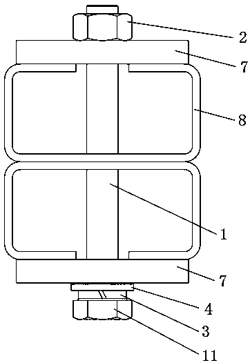
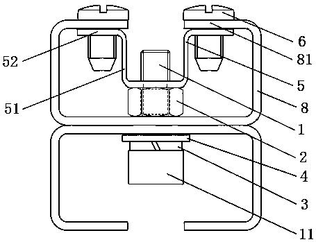
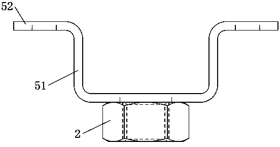
[0019] Specific embodiment 1 of the combined cabinet of the present invention, such as Figure 2~3 As shown, it includes two cabinets, the two cabinets have the same structure, and both include a cabinet frame and a wall panel installed on the cabinet frame. The cabinet frame has correspondingly arranged matching C-shaped profiles 8 with opposite openings, matching C The profile is provided with through holes at corresponding positions. One of the C-shaped materials 8 is equipped with a groove-shaped connector 5, which includes a groove-shaped piece 51 and a nut 2 welded on the outer surface of the groove bottom of the groove-shaped piece. The inner hole of the nut is connected to the other C-shaped material. The connecting bolt 1 which extends into the opening is adapted. The groove-shaped sheet body 51 is provided with an outer flange 52 at the position of the g...


PUM


Abstract

The invention relates to a combined cabinet. At least two cabinet body are included in that combine cabinet, each cabinet body comprises a cabinet body frame and a wall plate mounted on the cabinet body frame, the cabinet frames of two adjacent cabinets are provided with paired C-profiles which are arranged correspondingly and have opposite openings, A through-hole is arrange at that correspondingposition on the pair of C-shaped bar, One of the paired C-profiles is also provided with a groove-type connector therein, A groove of the groove-type connector is connected with an inner flange of acorresponding C-section, a groove bottom position of the groove-type connector is provided with a threaded hole for threaded connection with a connecting bolt threaded into the other one of the pairedC-sections through a through hole, and a groove inner space of the groove-type connector constitutes an accommodating space for accommodating the connecting bolt. The switch cabinet can be operated by only one person, which is convenient to operate and saves time and labor. The rear slot connector and bolt of the switch cabinet are all located in the C-section so as to avoid interference with thedoor lock and the hinge.

Description

Technical field [0001] The invention relates to a combined cabinet. Background technique [0002] In power distribution systems, switch cabinets with C-profile frames are widely used. There are usually two ways to connect switch cabinets together, one is welding connection, and the other is connection with bolts and nuts. Welding connection has very strict requirements on the consistency of the cabinets, and it will be very troublesome if the cabinets need to be separated after welding. The bolt connection requires two workers to work together, which is more troublesome. At the same time, due to the special structure of the profile, it is inconvenient to tighten the nut side, which makes the on-site cabinet connection work consume a lot of time and increase the labor intensity of the workers. [0003] An existing combined cabinet combined cabinet connection structure such as figure 1 As shown, the C-profiles 8 of the cabinet frames of the two switchgear are placed back to back, a...

Claims


Application Information

Patent Timeline
IPC IPC(8): H02B1/30
CPCH02B1/308
Inventor 王亚强赵宝红李桂芹陈起
Owner HENAN SENYUAN ELECTRIC CO LTD
Learn More