Flexible cutting system mechanism

A cutting system and flexible technology, applied in metal processing and other directions, can solve the problems of no cutter protection measures, unable to meet different types of cutting needs, affecting the cutting efficiency of the cutting machine, etc., to achieve the effect of protecting the blade

Inactive Publication Date: 2018-12-21
义乌市安倩科技有限公司
View PDF0 Cites 0 Cited by
  • Summary
  • Abstract
  • Description
  • Claims
  • Application Information

AI Technical Summary

Problems solved by technology

[0004] The traditional forced cutting cannot meet different kinds of cutting needs, and there are almost no protection measures for the cutting knife. The damage and replacement of the cutting knife will affect the cutting efficiency of the cutting machine

Method used


Image

  • Flexible cutting system mechanism
  • Flexible cutting system mechanism
  • Flexible cutting system mechanism

Examples


Embodiment 1

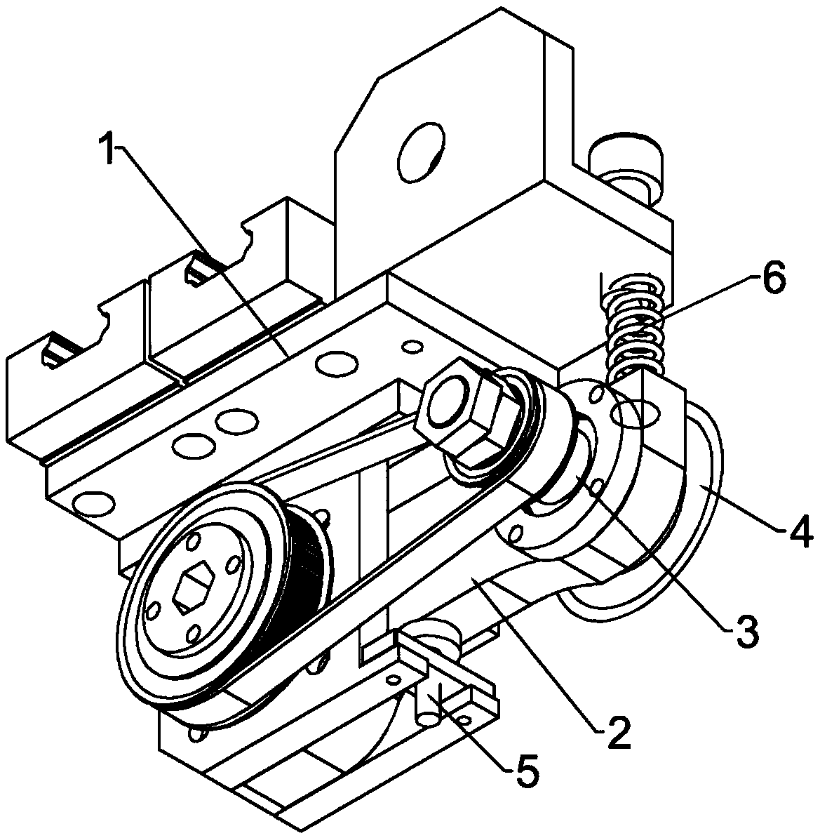
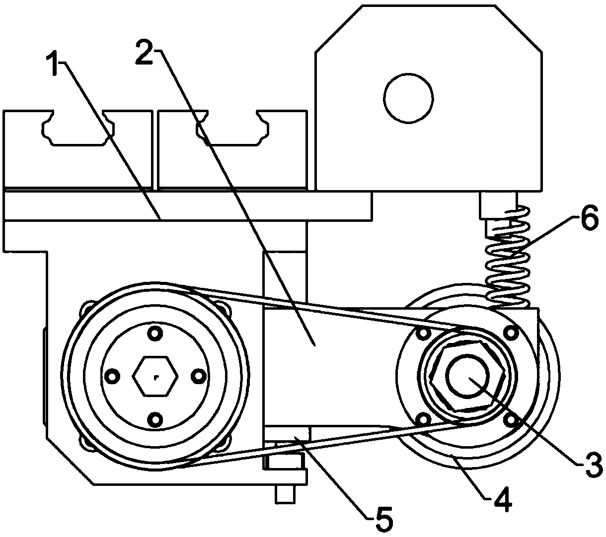
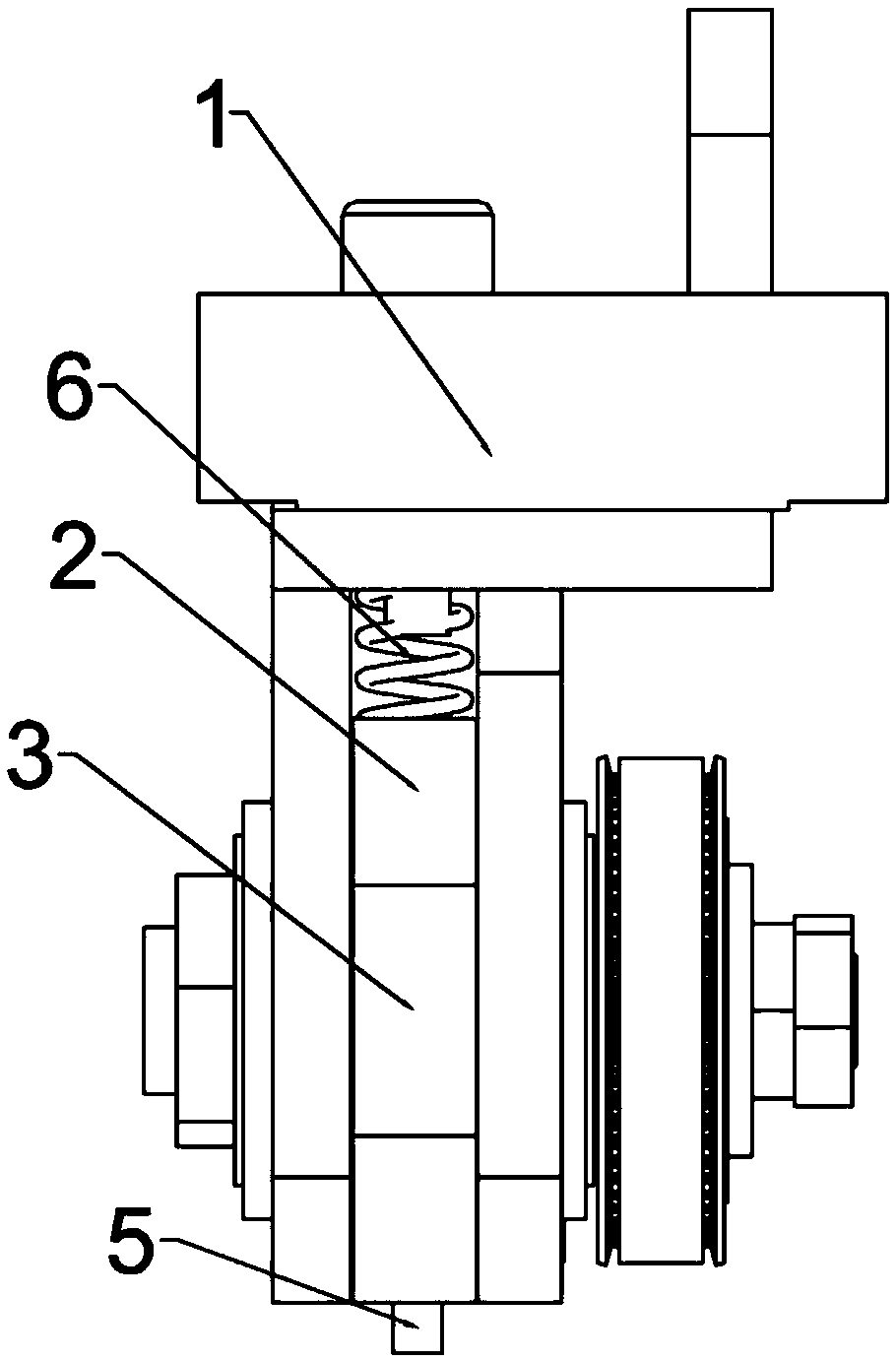
[0018] Example 1: Please refer to Figure 1-4 , a flexible cutting system mechanism, comprising a frame body 1, a swing arm 2 is rotatably connected to the bottom of the frame body 1, and a cutting blade 4 is fixedly connected to the outer end of the swing arm 2 through a positioning shaft 3 connected by rotation, and a cutting blade 4 is fixedly connected by driving the positioning shaft 3 To realize the rotation of the cutting blade 4, and then to cut, the bottom of the frame body 1 is screwed with a limit screw 5 that limits the swing angle of the swing arm 2, and the limit screw 5 limits the maximum swing limit of the swing arm 2, thereby determining the cutting contact. Position, between the frame body 1 and the outer end of the swing arm 2 is fixedly connected with an elastic member 6 that presses the swing arm 2 to move downward. The elastic member 6 enables the swing arm 2 to swing elastically, avoiding rigid cutting during the elastic swing process. Protect the blade....


PUM


Abstract

The invention discloses a flexible cutting system mechanism, and belongs to cutting equipment. The flexible cutting system mechanism comprises a rack body. A swing arm is rotationally connected to thelower portion of the rack body. A cutting blade is fixedly connected to the outer end of the swing arm through a rotationally connected positioning shaft. The lower portion of the rack body is in threaded connection with a limiting screw for limiting the swing angle of the swing arm. An elastic piece for pressing the swing arm to move downwards is fixedly connected between the rack body and the outer end of the swing arm. Compared with the prior art, the flexible cutting system mechanism has the beneficial effects that the cutting blade at the traditional fixing position is mounted at the outer end of the swing arm, elastic contact of the blade can be achieved through elastic limiting to the swing arm when the flexible cutting system mechanism conducts cutting, the blade is protected to the maximum extent, and various different cutting needs can be met.

Description

technical field [0001] The invention relates to a cutting device, in particular to a flexible cutting system mechanism. Background technique [0002] With the development of the modern mechanical processing industry, the requirements for cutting quality and precision are constantly improving, and the requirements for improving production efficiency, reducing production costs, and highly intelligent automatic cutting functions are also increasing. [0003] At present, the cutting of paper straws is basically rigid cutting. The power (such as a cylinder) directly presses down on the blade, and the blade directly forcibly cuts the paper tube. [0004] The traditional forced cutting cannot meet different kinds of cutting needs, and there are almost no protection measures for the cutting knife. The damage and replacement of the cutting knife will affect the cutting efficiency of the cutting machine. [0005] For this reason, those skilled in the art have proposed a flexible cutt...

Claims


Application Information

Patent Timeline
Patent Type & Authority Applications(China)
IPC IPC(8): B26D1/14B26D7/00
CPCB26D1/14B26D7/00
Inventor 余文华
Owner 义乌市安倩科技有限公司
Why Eureka
Try Eureka