Novel multi-cavity injection mold

An injection mold and a new type of technology, applied in the field of injection molding machines, can solve the problems of increasing manufacturing costs, wasting raw materials, increasing the probability of defective products, etc., and achieving the effects of low energy consumption, increased contact area, and low speed of cooling water flow

Inactive Publication Date: 2018-12-21
肖涵
View PDF0 Cites 0 Cited by
  • Summary
  • Abstract
  • Description
  • Claims
  • Application Information

AI Technical Summary

Problems solved by technology

[0004] The purpose of the present invention is to solve the technical problem that the plastics will agglomerate unevenly due to the insufficient stirring of the feeding material during the use of the existing injection mold, and provide a new type of multi-cavity injection mold. By arranging the stirring chamber, the rotating rod and the crushing leaf parts, the performance of the stirring can be improved, and it has a wide range of practicability, so as to solve the existing injection mold proposed in the above-mentioned background technology, in the process of use, due to the feeding stirring If the relationship is not thorough enough, the plastic will agglomerate unevenly, resulting in an increase in the probability of defective plastic products, thereby wasting raw materials, increasing manufacturing costs, reducing the working efficiency of injection molds, and poor use effects.

Method used


Image

  • Novel multi-cavity injection mold
  • Novel multi-cavity injection mold
  • Novel multi-cavity injection mold

Examples


Embodiment Construction

[0025] The following will clearly and completely describe the technical solutions in the embodiments of the present invention with reference to the accompanying drawings in the embodiments of the present invention. Obviously, the described embodiments are only some, not all, embodiments of the present invention. Based on the embodiments of the present invention, all other embodiments obtained by persons of ordinary skill in the art without making creative efforts belong to the protection scope of the present invention.

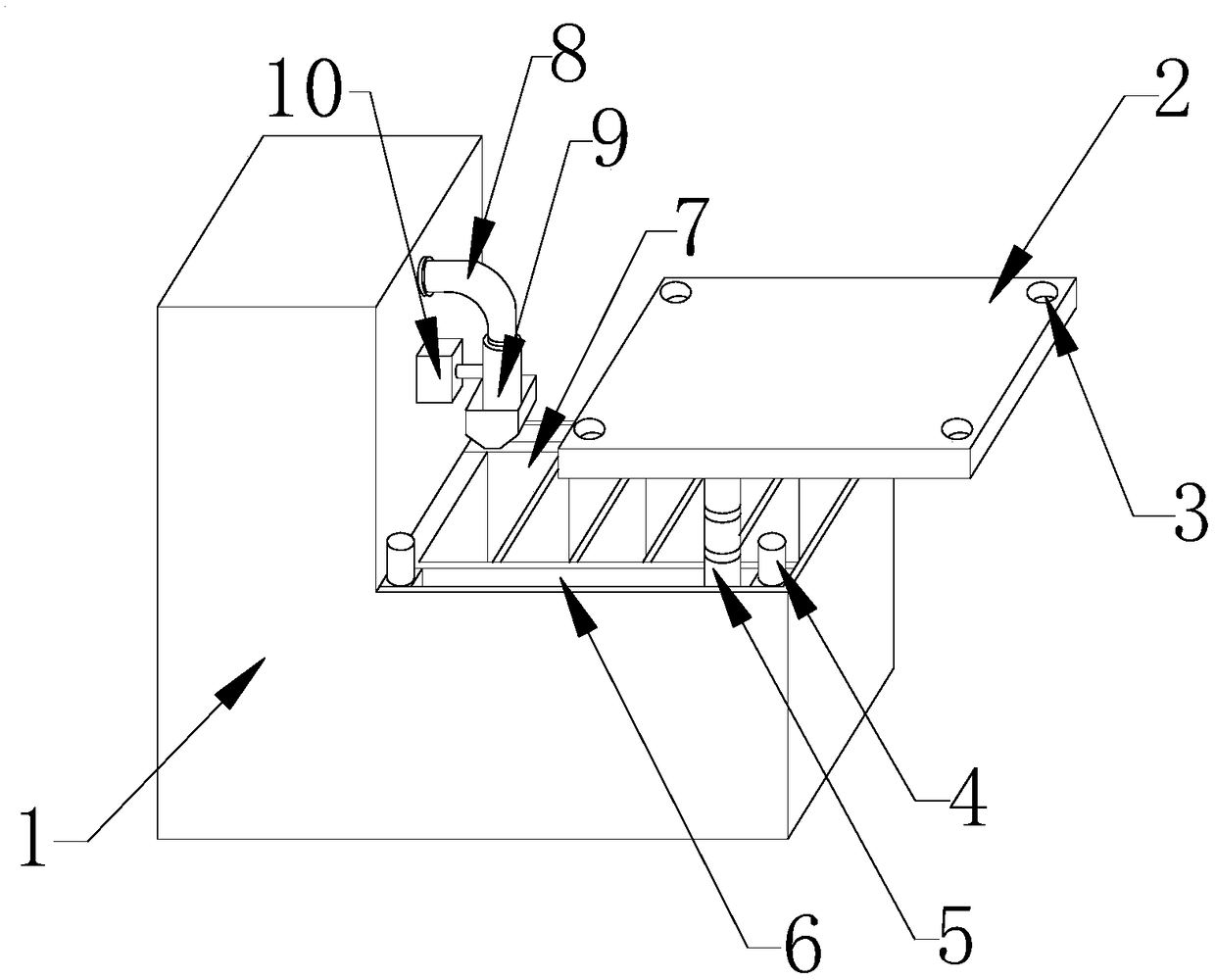
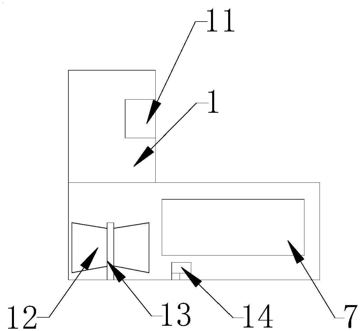
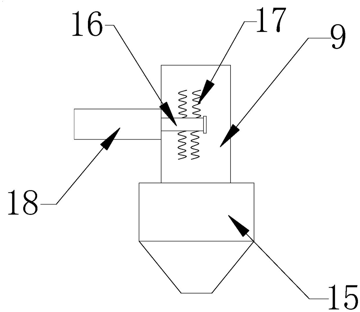
[0026] The injection mold 1 used in the present invention, the mold plate 2, the connecting column 4, the lifting connecting column 5, the slide rail 6, the mold cavity 7, the injection pipe 8, the stirring cavity 9, the connecting block 10, the motor 11, the blade 12, the rotating Column 13, cold water pump 14, feed hopper 15, rotating rod 16, crushing blade 17, connecting chamber 18, all can be purchased through market or private order gain.

[0027] The mod...


PUM


Abstract

The invention provides a novel multi-cavity injection mold. The novel multi-cavity injection mold comprises an injection mold body, a mold plate and mold plate holes; the mold plate is arranged at theupper end of the injection mold body, moreover, the mold plate is movably connected with the injection mold body, the mold plate holes are formed in the four corners of the surface of the mold plate,and the mold plate holes are connected with the mold plate in a penetrating mode. Each lifting connecting column is divided into three sections for lifting, moreover, the lifting connecting columns can be completely stored in sliding rails, by arranging each lifting connecting column with three sections for lifting, the mold plate can be well lifted and stored, moreover, the lifting connecting columns can be completely stored in the sliding rails so that the mold plate can be tightly attached to the injection mold body, the two sliding rails are arranged, moreover, the depth of each sliding rail is the height of one section of each lifting connecting column, by arranging the two sliding rails, the mold plate can move on the upper side of the injection mold body through the lifting connecting columns, the technical scheme is suitable for production and use of the novel multi-cavity injection mold, and a good development prospect is achieved.

Description

technical field [0001] The invention relates to the technical field of injection molding machines, in particular to an injection mold. Background technique [0002] Injection molding machine, also known as injection molding machine or injection machine. It is the main molding equipment for making thermoplastics or thermosetting plastics into various shapes of plastic products using plastic molding molds. The injection molding machine heats the plastic, applies high pressure to the molten plastic, and makes it shoot out to fill the mold cavity. According to the arrangement of injection device and clamping device, it can be divided into vertical type, horizontal type and vertical-horizontal combined type. [0003] In the process of using the existing injection molds, due to the insufficient feeding and mixing, the plastic will agglomerate unevenly, resulting in an increase in the probability of defective plastic products, thereby wasting raw materials, increasing manufacturi...

Claims


Application Information

Patent Timeline
Patent Type & Authority Applications(China)
IPC IPC(8): B29C45/26B29C45/17B29B13/10
CPCB29C45/2602B29B13/10B29C45/17B29C2045/1784B29C2045/2683
Inventor 肖涵
Owner 肖涵
Why Eureka
Try Eureka