a tire mold

A tire mold and mold shell technology, applied in the field of tire manufacturing, can solve the problems of unusable, affecting tire wear resistance, easy delamination and damage, etc., to facilitate wiring and dismantling, prolong service life, avoid extrusion or other problems damage effect

Active Publication Date: 2020-05-22
HIMILE MECHANICAL SCI & TECH (SHANDONG) CO LTD
View PDF4 Cites 0 Cited by
  • Summary
  • Abstract
  • Description
  • Claims
  • Application Information

AI Technical Summary

Problems solved by technology

[0002] When producing existing tires, it is necessary to strictly control the temperature and time of tire vulcanization. Poor control of the vulcanization temperature of green tire blanks will lead to tire scrapping and affect the qualified rate of tire quality
The vulcanization temperature is low, under the same time, it will produce undersulfur, undersulfur tire rubber reaction is not sufficient, the physical properties are poor, when the undersulfur is serious, it will be sticky, and it cannot be used. Poor, and easy to delaminate and damage; high vulcanization temperature, under the same time pressure, oversulfurization will occur, oversulfurized tire rubber will become brittle, poor wear resistance when used, and the phenomenon of chipping and chipping will also occur
[0003] Existing tire molds basically do not have the function of measuring the temperature of the mold. Even if there is, only a wire hole for temperature measurement of a tire is reserved on the mold. However, when the tire temperature is detected through the wire hole, it is necessary Inserting the temperature detection piece into the tire will damage the surface of the tire
The mold can only be used for temperature measurement. After the temperature measurement is completed, it cannot be used for vulcanization of normal tires.
However, when the temperature measurement line is arranged, it is not necessary to consider the non-temperature measurement working conditions of the mold, nor does it consider the influence of the mold opening and closing action on the line.

Method used


Image

  • a tire mold
  • a tire mold
  • a tire mold

Examples


Embodiment 1

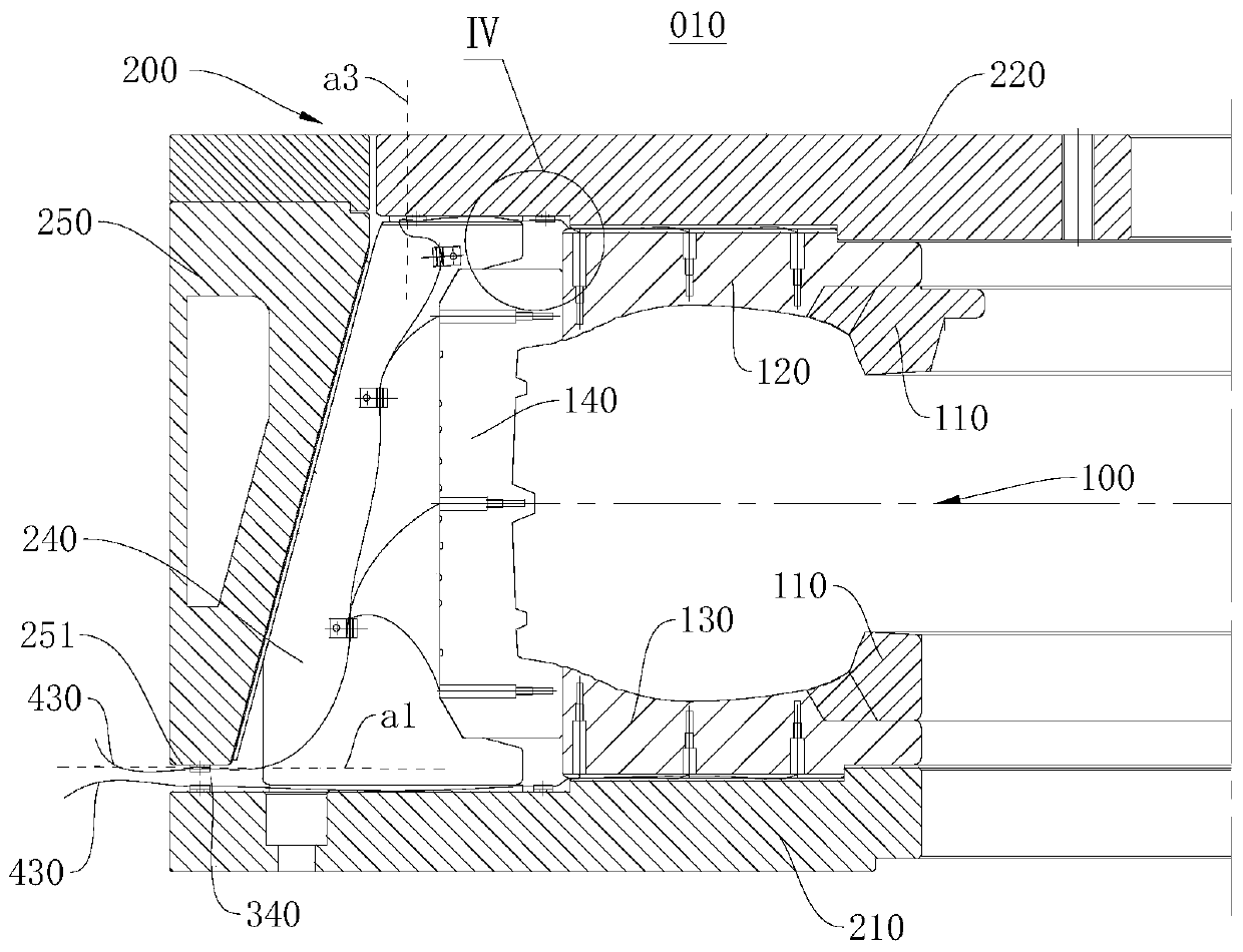
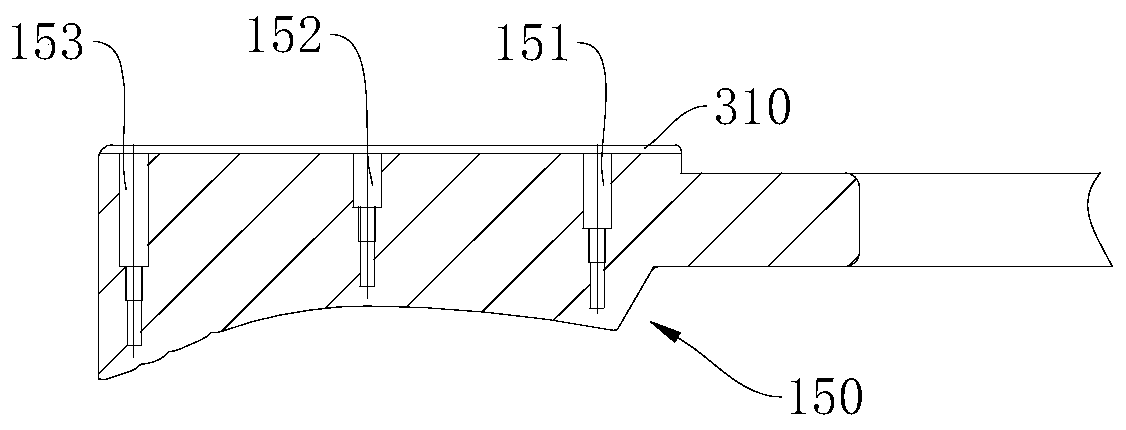
[0048] figure 1 A schematic diagram of the overall structure of the tire mold 010 provided in this embodiment. Please refer to figure 1, the present embodiment provides a tire mold 010 , which includes a mold shell assembly 200 and a cavity assembly 100 disposed in the mold shell assembly 200 . The upper side plate 120 of the cavity assembly 100 is provided with a temperature measuring hole 150 , and a temperature measuring element 410 is arranged in the temperature measuring hole 150 . The tire mold 010 has a first wire passage 310 communicating with the temperature measuring hole 150, the mold shell assembly 200 has a second wire passage 320 communicating with the first wire passage 310, and a temperature measuring line 430 connected to the temperature measuring element 410 Pass through the first wire passing slot 310 and the second wire passing slot 320 to be led out. By setting up the first line passage 310 and the second line passage 320 leading out the temperature mea...

Embodiment 2

[0068] Figure 11 A schematic diagram of the overall structure of the tire mold 010 provided in this embodiment. Please refer to Figure 11 , this embodiment also provides a tire mold 010, the structures of the mold shell assembly 200 and the cavity assembly 100 in the tire mold 010 are substantially the same as those of the tire mold 010 provided in Embodiment 1, and the same parts will not be repeated in this embodiment recorded.

[0069] In this embodiment, the formwork assembly 200 further includes an upper heating plate 230 disposed above the upper cover 220 , the wire passing hole 370 communicates with the first wire passing slot 310 , and penetrates through the upper cover 220 along the axial direction of the upper side plate 120 And upper hot plate 230 is set. The temperature measuring wires 430 of the temperature measuring elements 410 in the three temperature measuring holes 150 are introduced into the wire passing holes 370 through the first wire passing slots 31...


PUM


Abstract

The invention relates to the technical field of tyre manufacturing, and aims at providing a tyre mold. The provided tyre mold comprises a mold shell assembly and a cavity assembly arranged in the moldshell assembly. A temperature measuring hole is formed in an upper side plate of the cavity assembly and internally provided with a temperature measuring element. The tyre mold is provided with a first wire passing groove communicating with the temperature measuring hole. The mold shell assembly is provided with a second wire passing groove communicating with the first wire passing groove, and atemperature measuring wire connected with the temperature measuring element penetrates through the first wire passing groove and the second wire passing groove to be guided out. In the tyre mold preheating and tyre vulcanization process, the temperature of the tyre mold cavity face is monitored, and tyre damage is avoided. Meanwhile, the problems that the temperature measuring wire influences thework of the tyre mold, and the temperature measuring wire is extruded in the usage process are solved, and accordingly the service life of the tyre mold is prolonged.

Description

technical field [0001] The invention relates to the technical field of tire manufacturing, in particular to a tire mold. Background technique [0002] During the production of existing tires, the temperature and time of tire vulcanization need to be strictly controlled. If the temperature of green tire green tires is not well controlled, the tires will be scrapped and the qualified rate of tire quality will be affected. The vulcanization temperature is low, under the same time, it will produce undersulfur, undersulfur tire rubber reaction is not sufficient, the physical properties are poor, when the undersulfur is serious, it will be sticky, and it cannot be used. Poor, and easy to delaminate and damage; high vulcanization temperature, under the same time pressure, oversulfurization will occur, and oversulfurized tire rubber will become brittle, and it also has poor wear resistance during use, and it will also cause chipping and chipping. [0003] Existing tire molds basica...

Claims


Application Information

Patent Timeline
Patent Type & Authority Patents(China)
IPC IPC(8): B29D30/06
CPCB29D30/0606B29D30/0662B29D2030/0607
Inventor 张伟刘志兰赵阳杜平于泳
Owner HIMILE MECHANICAL SCI & TECH (SHANDONG) CO LTD
Why Eureka
Try Eureka