A method and apparatus for control a high beam lamp

A control method and technology of a control device, applied in signal devices, optical signals, transportation and packaging, etc., can solve the problem of poor anti-dazzling effect of high beams, affecting detection accuracy of obstacle positions, switching of high beams, and actual distance deviation Too big and other problems

Active Publication Date: 2018-12-21
BEIJING JINGWEI HIRAIN TECH CO INC
View PDF8 Cites 0 Cited by
  • Summary
  • Abstract
  • Description
  • Claims
  • Application Information

AI Technical Summary

Problems solved by technology

However, the monocular camera sensor can only collect the obstacle distance from one point, and there is often a large deviation between the obstacle distance collected and the actual distance of the obstacle, which seriously affects the detection accuracy and distance of the obstacle position. The switch of the light, the anti-glare effect of the high beam is not good

Method used


Image

  • A method and apparatus for control a high beam lamp
  • A method and apparatus for control a high beam lamp
  • A method and apparatus for control a high beam lamp

Examples


Embodiment Construction

[0068] The technical solutions in the embodiments of the present invention will be clearly and completely described below in conjunction with the accompanying drawings in the embodiments of the present invention. Obviously, the described embodiments are only some of the embodiments of the present invention, not all of them. Based on the embodiments of the present invention, all other embodiments obtained by persons of ordinary skill in the art without creative work all belong to the protection scope of the present invention.

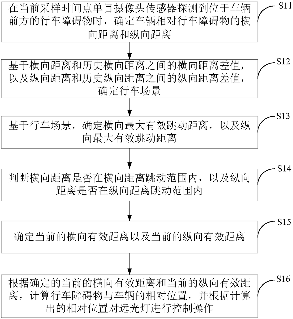
[0069] An embodiment of the present invention provides a high beam control method, referring to figure 1 , which can include:

[0070] S11. When the monocular camera sensor detects a driving obstacle in front of the vehicle at the current sampling time point, determine the lateral distance and longitudinal distance of the vehicle relative to the driving obstacle.

[0071] Wherein, the driving obstacle is an obstacle with anti-glare requirement, such as ...


PUM


Abstract

A method and apparatus for control a high beam lamp are provided, the method comprises the following steps: Based on the lateral distance and the historical lateral distance, longitudinal distance andhistorical longitudinal distance, determining a driving scenario, obtaining a lateral distance runout range and a longitudinal distance runout range under the driving scenario, determining The present lateral effective distance to be within the range of lateral distance runout, and determining the present longitudinal effective distance to be within the range of longitudinal distance runout. Calculating The relative position of the driving obstacle and the vehicle according to the present lateral effective distance and the present longitudinal effective distance, and controlling the high beamlamp according to the relative position. The present lateral effective distance and the longitudinal effective distance calculated by the technical scheme of the invention are closer to the real distance of the vehicle relative to the driving obstacle, The calculated relative position of the driving obstacle and the vehicle is more accurate, and the high beam control operation based on the relative position is more reasonable, which improves the position detection accuracy of the vehicle to the driving obstacle and the anti-dazzling effect of the high beam.

Description

technical field [0001] The present invention relates to the field of automotive electronics, more specifically, relates to a high beam control method and device. Background technique [0002] The high beam control system of the vehicle can switch the high beam and low beam adaptively according to whether there is an oncoming vehicle or a vehicle in front of the vehicle at night. The specific switching process is: when the vehicle is driving with the high beam, When the light control system recognizes that there is light from the headlights of the oncoming car or the vehicle in front of the vehicle, it considers that there is an obstacle in front of the vehicle. In order to avoid the dazzling effect of the high beam on the obstacles existing in front, thereby preventing accidents from happening. [0003] At present, the vehicle high beam control system mainly relies on the monocular camera sensor installed in front of the vehicle to collect the obstacle distance in front of ...

Claims


Application Information

Patent Timeline
Patent Type & Authority Applications(China)
IPC IPC(8): B60Q1/14
CPCB60Q1/14
Inventor 徐楠
Owner BEIJING JINGWEI HIRAIN TECH CO INC
Why Eureka
Try Eureka