
An earthquake-resistant limiting device of a bridge which is convenient to be replaced

A limit device, easy replacement technology, applied in the direction of bridges, bridge parts, bridge construction, etc., can solve the problems of reduced bridge anti-seismic performance, poor bridge anti-seismic performance, and inconvenient replacement of anti-seismic limit devices, so as to improve the anti-seismic performance, Guaranteed anti-seismic performance, easy to disassemble and replace

Pending Publication Date: 2018-12-21
BEIFANG UNIV OF NATITIES
View PDF1 Cites 9 Cited by
  • Summary
  • Abstract
  • Description
  • Claims
  • Application Information

AI Technical Summary

Problems solved by technology

[0003] The publication number is CN205000236U, which discloses a bridge anti-seismic limiting device, which at least includes a plurality of beam body embedded parts arranged at intervals outside the beam body web and a plurality of pier column embedded parts arranged outside the pier column. The embedded parts of the body and the embedded parts of the pier column are arranged in one-to-one correspondence, and the embedded parts of the beam body and the embedded parts of the pier column are respectively fixed and arranged on the beam body and the pier by penetrating anchor bolts. However, this device cannot offset the vibration through multi-stage buffering, which makes the seismic performance of the bridge poor. At the same time, the anti-seismic limit device is not easy to replace, so that it cannot be well maintained and repaired, which reduces the seismic performance of the bridge. performance

Method used


Image

  • An earthquake-resistant limiting device of a bridge which is convenient to be replaced
  • An earthquake-resistant limiting device of a bridge which is convenient to be replaced
  • An earthquake-resistant limiting device of a bridge which is convenient to be replaced

Examples


Embodiment Construction

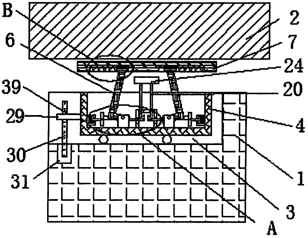
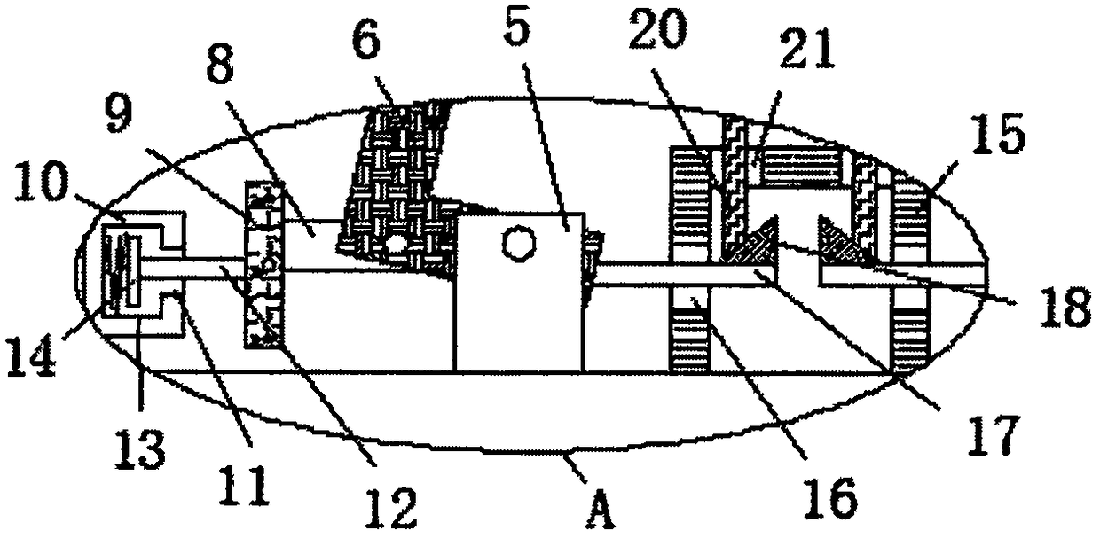
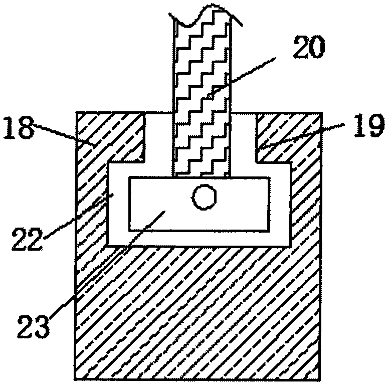
[0023] as attached Figure 1-5, a conveniently replaceable bridge anti-seismic limiting device, comprising: a bridge pier 1, an installation groove 3 is provided on the top side of the bridge pier 1, one side of the installation groove 3 is an opening, and an installation box 4 is movable installed in the installation groove 3, and the installation The top side of box 4 is provided with opening, and two fixed blocks 5 are fixedly installed on the bottom side inwall of installation box 4, and the top side of two fixed blocks 5 is all rotatably installed with L-shaped plate 6, and the two L-shaped plates 6 The top side extends to the outside of the installation groove 3 and is movably installed with the same support plate 7, the top side of the support plate 7 is movably installed with the bridge body 2, and the sides of the two L-shaped plates 6 away from each other are rotatably installed with a pull rod 8, The ends of the two pull rods 8 that are far away from each other are ...


PUM


Abstract

The invention relates to an earthquake-resistant limiting device of a bridge which is convenient to be replaced, includes piers, the top side of the pier is provided with a mounting groove, one side of the mounting groove is provided with an opening, A mounting box is movably mount in that mounting groove, the top side of the mounting box is provided with an opening, Two fixing blocks are fixedlyinstalled on the inner wall of the bottom side of the mounting box, L-shaped plates are rotatably installed on the top sides of the two fixing blocks, the top sides of the two L-shaped plates extend out of the mounting groove and are movably installed with the same support plate, the bridge body is movably installed on the top side of the support plate, and tie rods are rotatably installed on theside of the two L-shaped plates away from each other. The invention can effectively improve the vibration received by the bridge body during the earthquake through the multi-level cushioning, therebyensuring the seismic performance of the bridge body, prolonging the service life of the bridge body, and facilitating the disassembly and replacement of the installation box, thereby further improvingthe seismic performance of the bridge body.

Description

Technical field: [0001] The invention relates to the field of bridge anti-seismic technology, in particular to a bridge anti-seismic limiting device which is convenient to replace. Background technique: [0002] The damage to bridges caused by earthquakes is mainly caused by ground surface damage and bridge damage caused by earthquakes. In steep mountainous areas or sandy soil and soft clay river banks, landslides, bank slope sliding and rock rolling caused by strong earthquakes can damage bridges. In shallow saturated and loose sandy soil, earthquake action can easily cause sandy soil liquefaction, resulting in sudden or uneven sinking of the bridge, or even bridge toppling. Slope slipping, cracking and collapse will cause bridge damage. The earthquake damage of the bridge is due to the horizontal and vertical vibration of the bridge caused by the earthquake, resulting in damage and destruction of the bridge components, and even the collapse of the bridge. [0003] The pub...

Claims


Application Information

Patent Timeline
Patent Type & Authority Applications(China)
IPC IPC(8): E01D19/00E01D19/04
CPCE01D19/00E01D19/041Y02A30/30
Inventor 张立新丁晔赵帅包超
Owner BEIFANG UNIV OF NATITIES
Learn More