Anti-falling safety well lid assembly

An anti-fall, manhole cover technology, applied in water conservancy projects, artificial islands, underwater structures, etc., can solve problems such as failure to alleviate the loss of manhole covers

Active Publication Date: 2018-12-21
CHENGDU ZHIRONG ZHICHUANG INTPROP MANAGEMENT CO LTD
View PDF3 Cites 0 Cited by
  • Summary
  • Abstract
  • Description
  • Claims
  • Application Information

AI Technical Summary

Problems solved by technology

[0005] The technical problem to be solved by the present invention is: most of the prior art uses anti-falling nets to prevent people or foreign objects from falling into the well, and it does not

Method used


Image

  • Anti-falling safety well lid assembly
  • Anti-falling safety well lid assembly
  • Anti-falling safety well lid assembly

Examples


Embodiment 1

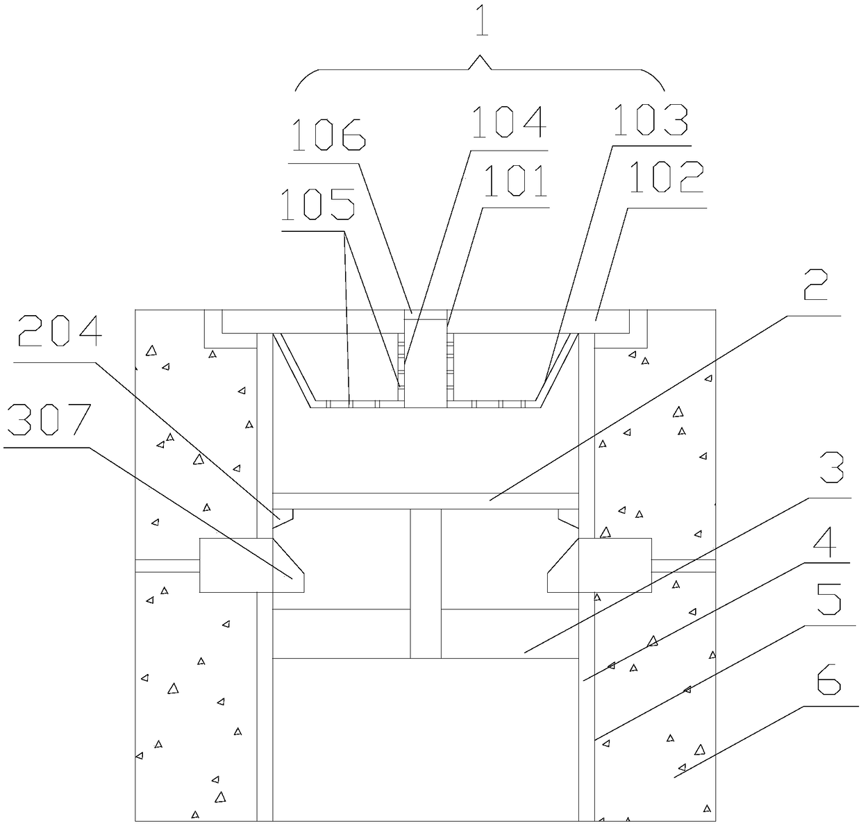
[0041] This embodiment provides an anti-fall safety well cover assembly, including a well cover 1 and an anti-fall screen 2. It includes a positioning cylinder 201, a plurality of radiating ribs 202 and a plurality of reinforcing ribs 203, and a plurality of radiating ribs 202 are uniformly distributed and fixed along the outer wall of the positioning cylinder 201 in a radial shape. The tube 201 is distributed on the coaxial center line to strengthen and fix the radial ribs 202, and a plurality of reinforcing ribs 203 are distributed at equal intervals along the radial direction of the positioning tube 201; the well cover 1 is provided with a through hole 101 for water circulation;

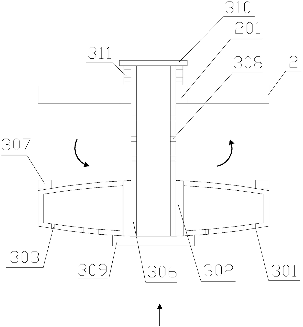
[0042] It also includes a buffer mechanism 3. The buffer mechanism 3 includes an outer sleeve 301, an inner sleeve 302, and a central tube 306. Both axial ports of the outer sleeve 301 are closed by sealing plates, and the inner sleeve 302 runs through the outer sleeve 301 in the axial direction. ...

Embodiment 2

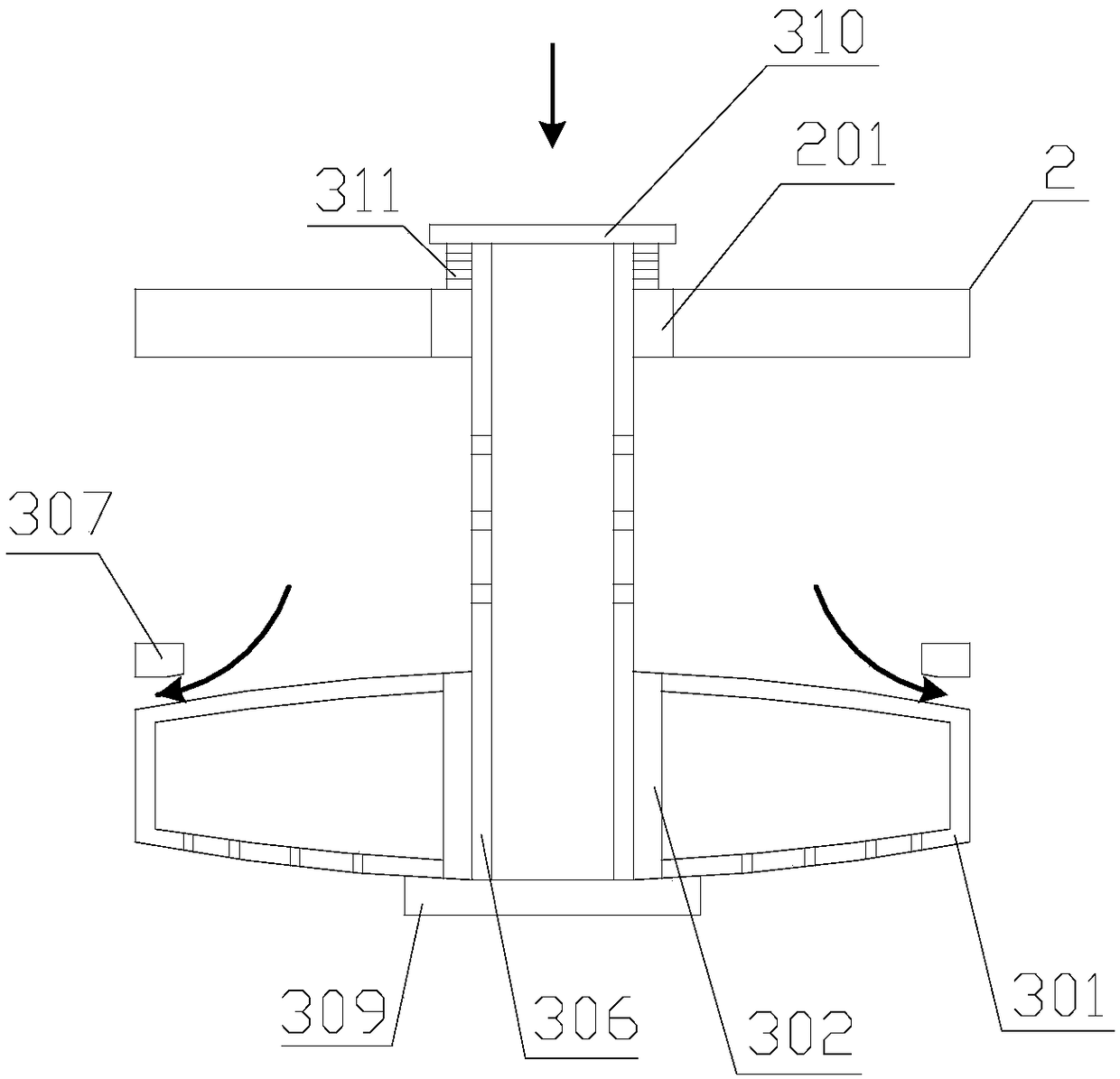
[0044] Further improvement on the basis of Embodiment 1, the sealing plates at both axial ends of the outer sleeve 301 are curved plates protruding outward, and the axial section of the outer sleeve 301 has a spindle structure. A rubber strip is arranged on the surface of the first limiting ring 307 facing the outer sleeve 301 , and the first limiting ring 307 is in contact with the lower surface of the outer sleeve 301 through the rubber strip. The axial end of the central tube 306 provided with bearings runs through the inner sleeve 302, and the end of the central tube 306 passing through the inner sleeve 302 is provided with a first baffle 309, and the first baffle 309 faces the surface of the outer sleeve 301 The ring is provided with a rubber strip, and the contact between the first baffle plate 309 and the outer sleeve 301 is through the rubber strip.

Embodiment 3

[0046] Further improvement on the basis of Embodiment 2, the central tube 306 runs through the axial end of the positioning cylinder 201 and is provided with a second baffle 310, the outer diameter of the second baffle 310 is larger than the inner diameter of the positioning cylinder 201; the central tube 306 runs through the positioning cylinder A buffer spring 311 is sheathed on the pipe section after 201 , one axial end of the buffer spring 311 is fixed on the second baffle plate 310 , and the other axial end is fixed at the top port of the positioning cylinder 201 . The central tube 306 and the positioning cylinder 201 are in clearance fit; the inner wall of the positioning cylinder 201 is concavely provided with several positioning grooves 205, and the plurality of positioning grooves 205 are distributed at equal intervals along the circumferential direction of the positioning cylinder 201 inner wall, and the extending direction of each positioning groove 205 is the same as...


PUM


Abstract

The invention discloses an anti-falling safety well lid assembly. A through hole used for water flowing is opened on the well lid; an anti-falling screen plate comprises a positioning barrel, a plurality of radiating ribs and a plurality of reinforcing ribs, wherein a plurality of radiating ribs and a plurality of reinforcing ribs are arranged in a spider web centering on the positioning barrel; two axial ends of the outer sleeve of the buffering mechanism are sealed by a sealing plate, the inner sleeve penetrates through the sealing plate at two axial ends of the outer sleeve and is sleeved in the outer sleeve; a plurality of first through holes are opened on the axial bottom end sealing plate of the outer sleeve; a plurality of leaf bending type strip-shaped shells are convexly arrangedon the surface of the axial top end sealing plate of the outer sleeve and are arranged in a turbine shape, and a plurality of liquid distribution holes are opened on the same side walls of the shells;the outer wall of one axial end of the center pipe is rotationally connected with the inner wall of the inner sleeve by a bearing and the other axial end is movably connected with the positioning barrel; and a plurality of second through holes are opened on the side wall of the center pipe. According to the anti-falling safety well lid assembly, the strong water flow impact force generated by overflow can be effectively dispersed and reduced, and casualties and vehicle damage since the well lid is jacked up and lost are avoided.

Description

technical field [0001] The invention relates to the technical field of urban road infrastructure, in particular to an anti-fall safety manhole cover assembly. Background technique [0002] Manhole cover, the covering on the road, can be seen everywhere in the streets and alleys of cities and towns. It is used to cover roads or deep wells in homes to prevent people or objects from falling. According to the material, it can be divided into metal manhole covers, high-strength fiber cement concrete manhole covers, resin manhole covers, etc. Usually round. It can be used in green belts, sidewalks, motorways, docks, alleys, etc. [0003] Due to the short-term heavy rainfall and insufficient capacity of drainage pipes, once the pipe network leaks water, the impact force will be greater, and the manhole cover will be lifted up or even fly. Passers-by cannot see the situation under their feet. Accidents of washing away occurred, and vehicle damage and personal casualty accidents o...

Claims


Application Information

Patent Timeline
IPC IPC(8): E02D29/14
CPCE02D29/14E02D29/1436E02D29/1481
Inventor 黄欢
Owner CHENGDU ZHIRONG ZHICHUANG INTPROP MANAGEMENT CO LTD
Why Eureka
Try Eureka