
Drainage device for municipal plaza

A technology for drainage devices and squares, applied in water supply devices, drainage structures, waterway systems, etc., can solve the problems of exposed drains on the surface, blocked drains, and people falling, so as to ensure cleanliness, avoid tripping, and prevent accumulation. Effect

Active Publication Date: 2018-12-21
云南正浩建设工程有限公司
View PDF8 Cites 4 Cited by
  • Summary
  • Abstract
  • Description
  • Claims
  • Application Information

AI Technical Summary

Problems solved by technology

[0002] In the underground of large public places such as streets and squares, it is often necessary to lay accessible drainage systems to ensure the cleanliness and safety of these places; especially in severe weather such as heavy rain, the drainage efficiency of streets and squares directly affects the entire city and the entire traffic The operating health of the system; the current drainage scheme is to set up drains around the streets and squares, and cover the drains with inspection well covers, and the water flows into the drainage system after passing through the inspection well covers; because there are diversion holes on the inspection well covers, The sundries and rubbish in squares and streets are easy to enter the drainage system, which eventually causes the blockage of the drain outlet; also because the manhole cover is provided with diversion holes, the structure of the manhole cover is not firm, often cracked, damaged, broken The manhole cover is easy to block the sewer pipe, and at the same time exposes the drain to the surface, which is prone to the danger of people falling; in addition, the manhole cover is heavy and inconvenient to maintain and replace; at the same time, the exposed manhole cover does not match the clean streets. Affect the orderliness and beauty of the street; therefore, traditional drainage devices are increasingly unable to adapt to modern urban construction

Method used


Image

  • Drainage device for municipal plaza
  • Drainage device for municipal plaza
  • Drainage device for municipal plaza

Examples


Embodiment

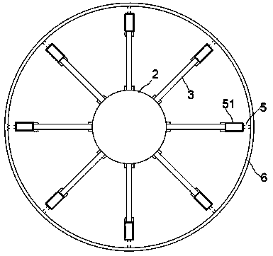
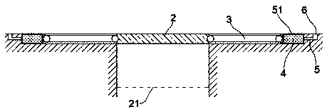
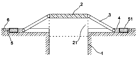
[0015] exist Figure 1 to Figure 3 In the shown embodiment, this municipal square drainage device includes a drain port 1, a cover plate 2 matched with the drain port 1; the outer edge of the cover plate 2 is provided with an annular isolation sieve plate 21, and The outer ring diameter matches the inner diameter of the drain port 1;

[0016] A push rod 3 is connected to the outer periphery of the cover plate 2, and each push rod 3 extends outward along the axis of the cover plate 2; a drive bar 4 is connected to the outer end of the push rod 3, and the push Both ends of the rod 3 can rotate around the axis in the vertical plane; the drive bar 4 is slidably arranged in the positioning slider 51, and the positioning slider 51 is fixedly embedded on the ground, and the positioning slider 51 is formed by Made of transparent material; on the positioning slide 51, there is a diversion hole 5 connected with the ground; on the outside of the drain 1, there is a guide ring groove 6, ...


PUM


Abstract

The invention relates to a drainage device for a municipal plaza. The drainage device comprises a drainage port and a cover plate matched with the drainage port; pushing rods are in shaft connection with the periphery of the cover plate, and all the pushing rods extend outwards in the axis of the cover plate; driving strips are in shaft connection with the outer ends of the pushing rods, and the two ends of the pushing rods can rotate around axes in vertical planes; the driving strips are slidingly arranged in positioning sliding barrels which are fixedly embedded into the ground and made of transparent materials; flow guiding holes communicated with the earth surface are formed in the positioning sliding barrels; the driving strips are made from water-absorption expanding materials and expand in the axis direction of the positioning sliding barrels after absorbing water. The drainage device is novel in structure and unique in principle, the drainage port can be intelligently opened and closed, rainwater dredging is guaranteed, debris blocking can be effectively prevented, peculiar smells are reduced, and meanwhile the effect of beautifying roads and the plaza is realized.

Description

technical field [0001] The invention relates to the field of municipal engineering drainage, in particular to a drainage device. Background technique [0002] In the underground of large public places such as streets and squares, it is often necessary to lay accessible drainage systems to ensure the cleanliness and safety of these places; especially in severe weather such as heavy rain, the drainage efficiency of streets and squares directly affects the entire city and the entire traffic The operating health of the system; the current drainage scheme is to set up drains around the streets and squares, and cover the drains with inspection well covers, and the water flows into the drainage system after passing through the inspection well covers; because there are diversion holes on the inspection well covers, The sundries and rubbish in squares and streets are easy to enter the drainage system, which eventually causes the blockage of the drain outlet; also because the manhole ...

Claims


Application Information

Patent Timeline
IPC IPC(8): E03F5/04E03F5/06
CPCE03F5/0404E03F5/06
Inventor 胡振强
Owner 云南正浩建设工程有限公司
Learn More