
Supplemental window for fenestration

a technology of supplemental windows and fenestration, applied in the field of supplemental windows, can solve the problems of preventing more widespread and effective utilization, reducing the cost of supplemental windows, and difficult manufacturing of size customization, so as to achieve the effect of maximizing thermal insulation properties

Active Publication Date: 2016-01-12
WEXENERGY
View PDF278 Cites 12 Cited by
  • Summary
  • Abstract
  • Description
  • Claims
  • Application Information

AI Technical Summary

Benefits of technology

The present invention is a supplemental window for existing windows that reduces heat transfer and maintains visual transparency. The window is made of plastic and attached to the existing window using a frame and seal. The window is designed to not impair the operation of the existing window or treatments. The supplemental window can also improve energy efficiency and provide temporary fresh air to the space surrounding the window. The invention is easy to install and remove, and provides an aesthetically pleasing appearance.

Problems solved by technology

While these approaches have shown considerable improvement in building energy efficiency, significant problems prevent more widespread and effective utilization.
Several problems exist in the approaches to minimizing heat transfer through fenestration.
Supplemental window elements known in the art either require the end user to customize supplemental window elements to the dimensions of each window at the site of installation or are designed in ways that make size customization difficult in manufacturing.
In addition, such window films often must be mounted in such a way that inhibits the operability of non-fixed windows.
Other window films, such as tints, infrared or ultraviolet reflective, or low-e films, generally adhere directly to the window pane and do not allow for simultaneous formation of an insulating layer.

Method used


Image

  • Supplemental window for fenestration
  • Supplemental window for fenestration
  • Supplemental window for fenestration

Examples


Embodiment Construction

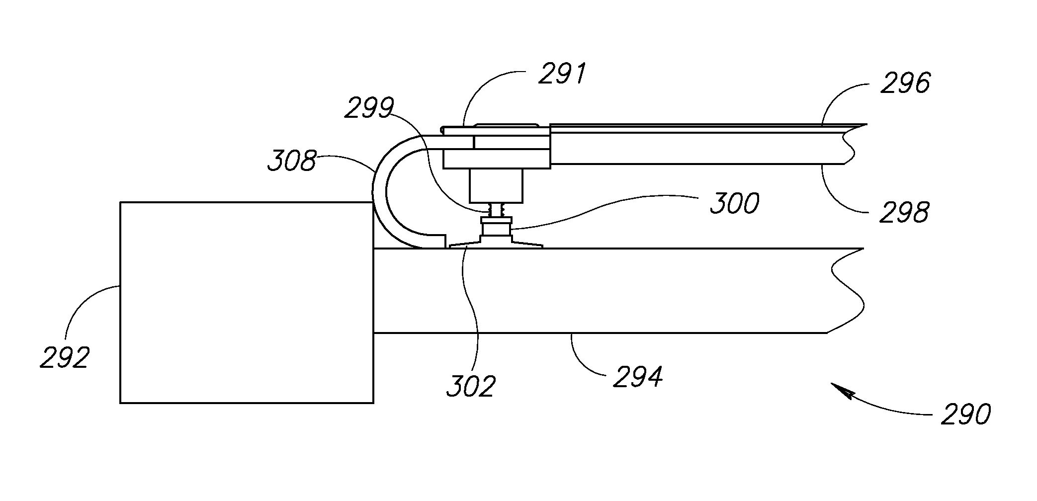
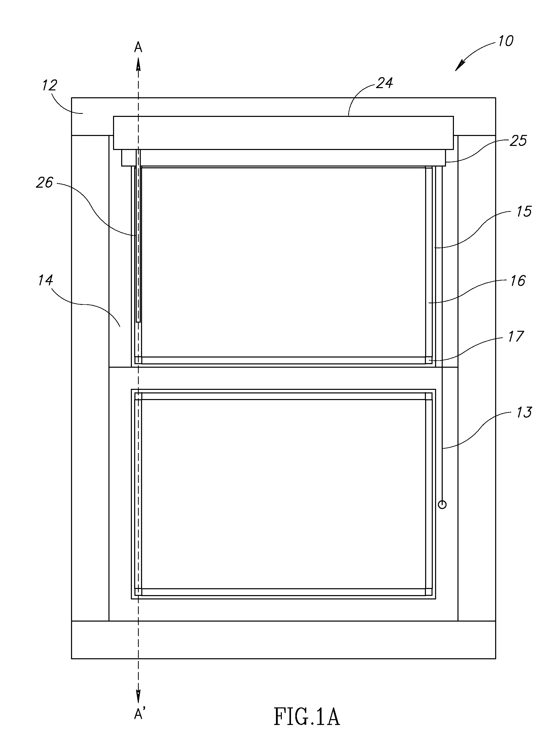
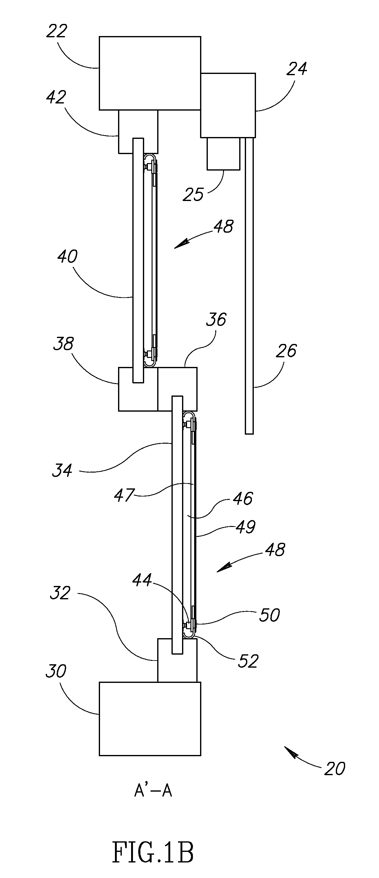
[0039]The present invention provides for several embodiments for mounting of sheet material in or over fenestration and substantially enclosing a volume of gas in or adjacent to the fenestration. In the present invention, the sheet material, a spacer of predetermined length, a supplemental window frame and a compressible perimeter closure together provide a supplemental window unit that substantially encloses and traps a volume of gas (typically air). Optionally, the clear sheet material may function as a portion of the compressible perimeter closure. In one embodiment, the spacer may contact or attach to the window pane of the fenestration. The sheet material can be any desired type of material such as, but not limited to, clear, non-opaque, visible light transmitting, infrared reflecting, material having minimal refractive distortion when viewed from the interior side of the window, etc. The extent of visible light transmission properties of the sheet material is not critical to t...


PUM


Abstract

A supplemental window for fenestration suitable for use with existing windows. The supplemental window, in one embodiment, comprises a frame with plastic sheet material stretched across it. An attachment mechanism secured to the frame functions to fasten the supplemental window to an existing window. The attachment mechanism can be a suction cup or adhesive for example. A seal attached to the frame functions to trap a volume of air between the window pane and the plastic sheet material. An aesthetic covering and draft inhibiting mechanism are also provided. The supplemental window is configured such that the layer of trapped air is of an optimum thickness of 0.15 to 0.75 inches to maximize thermal insulation properties of the supplemental window.

Description

REFERENCE TO PRIORITY APPLICATION[0001]This application is a continuation-in-part of U.S. application Ser. No. 13 / 735,449, filed Jan. 7, 2013, now U.S. Pat. No. 8,923,650, entitled “System and Method of Measuring Distances Related to an Object,” incorporated herein by reference in its entirety.FIELD OF THE INVENTION[0002]The present invention relates generally to fenestration and in particular to a supplemental window and related method of construction for use with existing windows.BACKGROUND OF THE INVENTION[0003]In recognition of the ecological and cost impact of fossil fuels and other conventional energy sources, significant effort has been expended in developing methods for more efficient use of such energy sources. An important area of energy use for which greater energy efficiency is needed is the heating and cooling of spaces in which human activity is desired. Many approaches have been developed to decrease the amount heat transfer through the shell of such spaces. One of th...

Claims


Application Information

Patent Timeline
Patent Type & Authority Patents(United States)
IPC IPC(8): E06B3/28B60J1/00E06B9/00
CPCE06B3/28B60J1/002E06B2009/005
Inventor WEXLER, RONALD MYRONMETELSKY, ALAN SCOTT
Owner WEXENERGY
Learn More