A Microcone-Based Electromagnetic Railgun Rail

An electromagnetic rail gun and rail technology, which is applied to electromagnetic launchers, weapon types, weapons without explosives, etc., can solve problems such as armature loss of contact, and achieve the effects of ensuring uniformity, good protection, and improving power utilization.

Active Publication Date: 2021-08-10
BEIJING MECHANICAL EQUIP INST
View PDF0 Cites 0 Cited by
  • Summary
  • Abstract
  • Description
  • Claims
  • Application Information

AI Technical Summary

Problems solved by technology

[0005] In view of the above analysis, the present invention aims to provide a micro-cone-based electromagnetic rail gun track to solve the problem that the armature loses contact at the end of the track in the prior art

Method used


Image

  • A Microcone-Based Electromagnetic Railgun Rail
  • A Microcone-Based Electromagnetic Railgun Rail
  • A Microcone-Based Electromagnetic Railgun Rail

Examples


Embodiment Construction

[0030] Preferred embodiments of the present invention will be described in detail below in conjunction with the accompanying drawings, wherein the accompanying drawings constitute a part of the application and together with the embodiments of the present invention are used to explain the principle of the present invention and are not intended to limit the scope of the present invention.

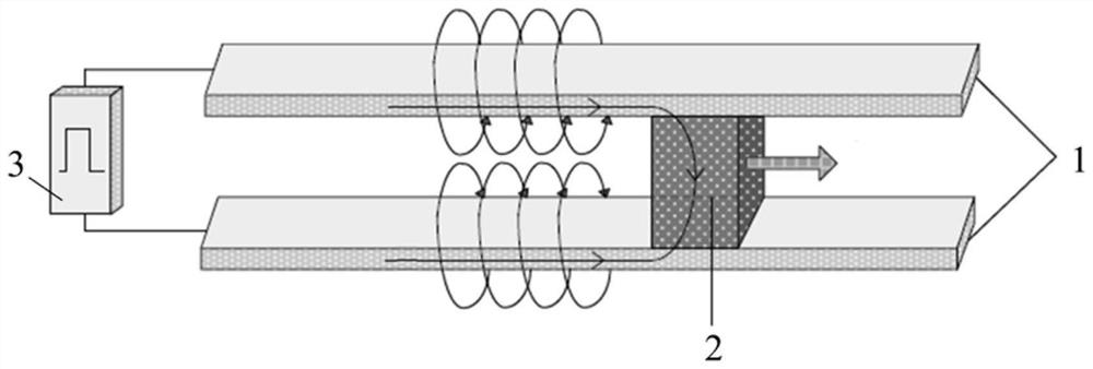
[0031] From the analysis of the basic principle of the electromagnetic railgun, it is equivalent to a single-turn current motor, which is a launcher that propels the armature 2 and accelerates the projectile by means of electromagnetic force. The working principle of the entire electromagnetic railgun system is as follows figure 1 shown.

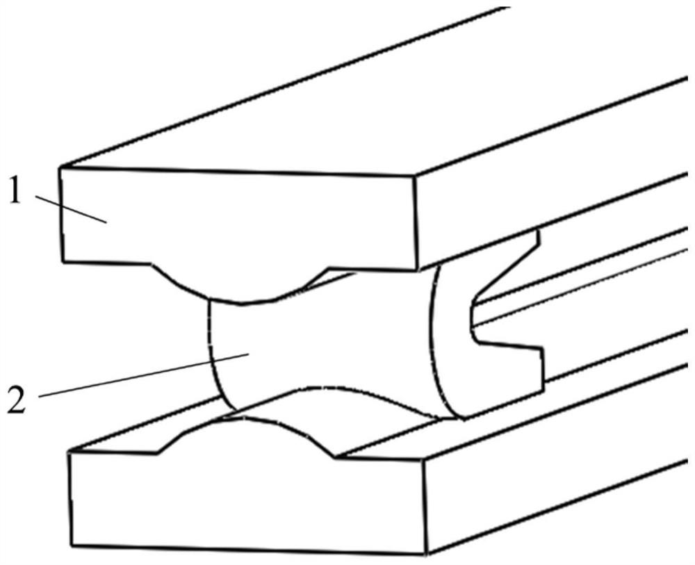
[0032] The electromagnetic railgun consists of two parallel-connected high-current fixed rails and an armature 2 that maintains good electrical contact with the rails and can slide along the axis of the rails 1 . When the power supply is connected, the curr...


PUM


Abstract

The invention relates to a microcone-based electromagnetic rail gun rail, which belongs to the field of electromagnetic rail guns and solves the problem that an armature loses contact at the end of the rail in the prior art. The track includes a first track and a second track, and the armature of the electromagnetic railgun moves between the first track and the second track; the distance between the tracks near the muzzle end is smaller than the distance between the tracks far from the muzzle end. During the launching process of the rail gun, the above design can increase the effective contact area of ​​the pivot rail, reduce the sparking and ablation caused by the detachment of the pivot rail in the middle and rear sections of the rail, reduce the heat generation in the gun bore, and play a significant role in the rail. Good protection.

Description

technical field [0001] The invention relates to the technical field of electromagnetic railguns, in particular to a microcone-based electromagnetic railgun rail. Background technique [0002] The electromagnetic railgun is composed of two high-current fixed rails connected in parallel and an armature that maintains good electrical contact with the rails and can slide along the axis of the rails. When a power source is applied, current flows through the armature along one track and back through the other, thus forming a closed circuit. When a large current flows through two parallel rails, a strong magnetic field is generated between the two rails. This magnetic field interacts with the current flowing through the armature to generate an electromagnetic force that pushes the armature and the projectile placed in front of the armature along the rails. Accelerate the movement to obtain high speed. During launch, the orbit will be subjected to electromagnetic expansion forces....

Claims


Application Information

Patent Timeline
Patent Type & Authority Patents(China)
IPC IPC(8): F41B6/00
CPCF41B6/006
Inventor 刘辉王爱涛耿轶青
Owner BEIJING MECHANICAL EQUIP INST
Why Eureka
Try Eureka