Touch Panel

A touch panel and touch area technology, applied in the field of touch technology, can solve the problems of increased electrode signal, uneven and poor capacitance distribution, and achieve the effect of uniform capacitance distribution

Active Publication Date: 2018-12-21
WUHAN CHINA STAR OPTOELECTRONICS SEMICON DISPLAY TECH CO LTD
View PDF5 Cites 5 Cited by
  • Summary
  • Abstract
  • Description
  • Claims
  • Application Information

AI Technical Summary

Problems solved by technology

[0007] The embodiment of the present application provides a touch panel to solve the problem that the electrodes in the metal grid structure of the existing touch panel do not completely cover the touch area, resulting in uneven capa

Method used


Image

  • Touch Panel
  • Touch Panel
  • Touch Panel

Examples


Embodiment Construction

[0032] Please refer to the drawings in the accompanying drawings, wherein like reference numerals refer to like components. The following description is based on illustrated specific embodiments of the present application, which should not be construed as limiting other specific embodiments of the present application that are not described in detail here.

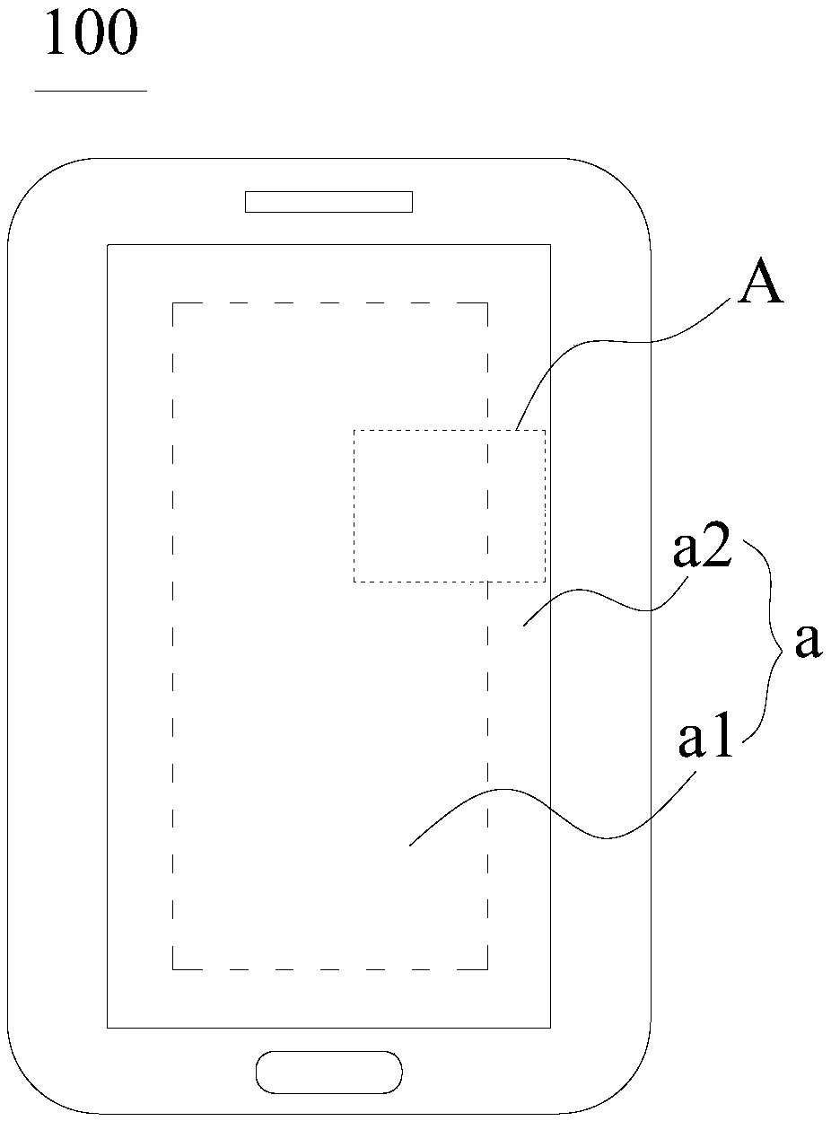
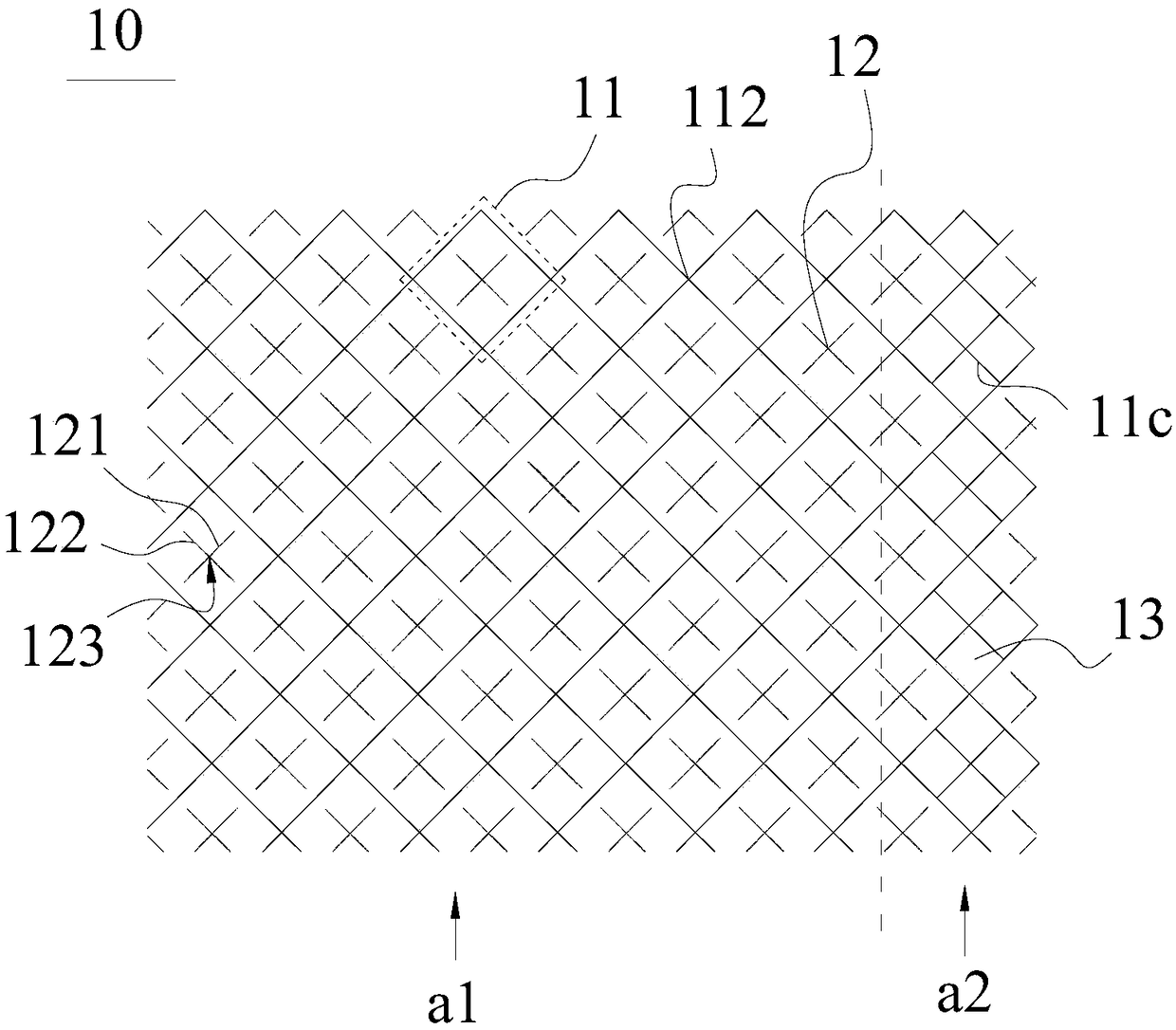
[0033] Please refer to figure 2 and image 3 , figure 2 It is a schematic structural diagram of the first embodiment of the touch panel of the present application; image 3 for figure 2 Enlarged view of A. In the first embodiment of the touch panel of the present application, the touch panel 100 includes a substrate 13 and a touch area a disposed on the substrate 13 . The touch area a includes a metal grid structure 10 . The metal grid structure 10 includes a plurality of unit grids 11 and dummy units 12 .

[0034] A plurality of unit grids 11 are connected to each other. The dummy cell 12 includes at least one f...


PUM


Abstract

The invention provides a touch panel. The touch panel includes a touch area, a metal mesh structure is arrange on the touch control area, the metal mesh structure includes touch electrodes and a dummyunit, the touch electrode includes a plurality of cell grids connected to each other, the dummy unit includes at least one first line, at least one second line, and an intersection formed by intersecting the first line and the second line. The dummy unit is arranged in the cell grid. The dummy unit has a gap distance between the dummy unit and the cell grid, and at least part of the dummy unit isarranged in the cell grid. The invention uniformizes the distribution of the capacitance by covering the whole touch area with the grid-shaped touch electrode; the dummy cell is arranged in the cellgrid of the touch electrode, so that the dummy cell is arranged dispersedly, and the influence when the touch electrode is short-circuited can be effectively reduced.

Description

technical field [0001] The present application relates to a touch technology, in particular to a touch panel. Background technique [0002] With the development of touch technology, touch panel technology has been applied in the field of display, such as touch display devices such as mobile phones, IPADs, and touch screens. [0003] The touch panel is arranged in the touch display device, and the touch panel includes a substrate, grid-shaped driving electrodes and grid-shaped sensing electrodes arranged on the substrate, and first grids arranged at intervals between the driving electrodes The second grid-like filling body and the second grid-like filling body arranged at intervals between the sensing electrodes; [0004] Wherein, the grid-like driving electrodes and the first grid-like filling body, and the grid-like sensing electrodes and the second grid-like filling body all form a metal grid structure. [0005] In metal grid structures, such as figure 1 , because elect...

Claims


Application Information

Patent Timeline
IPC IPC(8): G06F3/044
CPCG06F3/0412G06F3/044
Inventor 马亚龙
Owner WUHAN CHINA STAR OPTOELECTRONICS SEMICON DISPLAY TECH CO LTD
Why Eureka
Try Eureka