Mixed mode lane system

A hybrid mode and lane technology, applied in the related fields of ETC lanes, can solve the problems of low lane utilization, inability to charge trucks, low toll collection and traffic efficiency, etc., and achieve the effect of improving traffic capacity and reducing costs.

Pending Publication Date: 2018-12-21
GUANGZHOU HUAGONG INFORMATION SOFTWARE
View PDF7 Cites 0 Cited by
  • Summary
  • Abstract
  • Description
  • Claims
  • Application Information

AI Technical Summary

Problems solved by technology

The weighing toll system is installed in the toll lane, mainly for trucks, which need to be parked for manual toll collection, resulting in congestion of toll booths and low efficiency of toll collection and traffic
The ETC non-stop toll collection system is installed in an independent ETC toll lane. It is mainly aimed at passenger cars. It can automatically complete the toll collection work according to the vehicle model without parking. The toll and traffic efficiency is high, but it cannot charge for trucks. low rate

Method used


Image

  • Mixed mode lane system
  • Mixed mode lane system
  • Mixed mode lane system

Examples


Embodiment 1

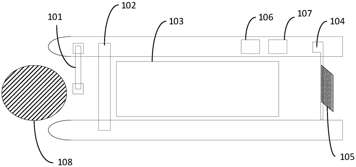
[0017] Embodiment 1 of the present invention provides a mixed-mode lane system, which is suitable for passing passenger cars (passenger cars are a general term for small vehicles, used to refer to vehicles that only need to consider the formal mileage when deducting fees, and do not need to consider the weight), and The lane where trucks (used to refer to vehicles whose mileage and weight need to be considered for deduction) are allowed to pass.

[0018] Wherein, the lane provided in this embodiment refers to the lane installed with ETC (Electronic Toll Collection, electronic toll collection system). ETC establishes short-range communication between the vehicle-mounted electronic tag installed on the windshield of the vehicle and the microwave antenna installed on the ETC lane of the toll station, and uses computer networking technology to carry out background settlement processing with the bank, so that the vehicle passes through the road and bridge toll station without needin...

Embodiment 2

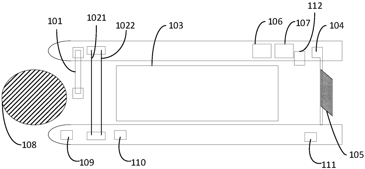
[0051] image 3 It is a schematic diagram of a mixed-mode lane system provided by Embodiment 2 of the present invention. This embodiment is a refinement based on the first embodiment. refer to image 3 , the hybrid mode lane system specifically further includes a first grating 1021 , a second grating 1022 , a camera device 109 , a front-end display 110 and a rear display 111 .

[0052] In this embodiment, the grating group is subdivided into a first grating 1021 and a second grating 1022 arranged along the driving direction of the lane; the first grating 1021 and the second grating 1022 are respectively connected to the toll collection device 107 . The distance between the first grating 1021 and the second grating 1022 is 0.5 meters. Specifically, when the first grating or the second grating is blocked, a level signal is transmitted to the charging device. The toll collection device judges whether the vehicle is traveling along the lane or in the reverse direction accordin...


PUM


Abstract

The invention discloses a mixed mode lane system. The system comprises an antenna, a grating group, weighing equipment, a railing and a sensor arranged along the lane direction, as well as toll collection equipment and license plate senseless payment equipment, wherein the toll collection equipment generates a first payment signal according to a first type of vehicle, and carries on first paymentsignal deduction on the vehicle through the antenna; the toll collection equipment also generates a second payment signal according to a second type of vehicle, and carries on second payment signal deduction on the vehicle; the toll collection equipment controls the railing to rise after the deduction is successful, and controls the railing to drop after the vehicle leaves; and the toll collectionequipment maintains a vehicle weight buffer queue according to a running direction signal and a vehicle departure signal. Through adoption of the system, the problems that a current ETC system cannoteffectively realize non-stop toll collection of freight cars and cannot simultaneously meet mixed queuing for weighing and toll collection of freight cars and buses are solved.

Description

technical field [0001] Embodiments of the present invention relate to technologies related to ETC lanes, and in particular to a mixed-mode lane system. Background technique [0002] ETC (Electronic Toll Collection) is a non-stop electronic toll collection system. ETC special lanes are used for vehicles equipped with ETC on-board devices. Electronic toll collection is adopted. ETC non-stop toll collection system is currently the most advanced road and bridge toll collection method in the world. Through the microwave-specific short-range communication between the vehicle-mounted electronic tag installed on the windshield of the vehicle and the microwave antenna on the ETC lane of the toll station, the computer networking technology is used to carry out background settlement processing with the bank, so that the vehicle can pass through the road and bridge toll station without stopping For the purpose of paying road and bridge tolls, when the vehicle passes through the toll sta...

Claims


Application Information

Patent Timeline
Patent Type & Authority Applications(China)
IPC IPC(8): G07B15/06
CPCG07B15/063
Inventor 谢海强罗庆异徐晓帆张建文李计管
Owner GUANGZHOU HUAGONG INFORMATION SOFTWARE
Why Eureka
Try Eureka