Display control device, display apparatus, television receiver, control method for display control device, control program, and recording medium
A display control and program control technology, applied to color TV parts, color signal processing circuits, brightness and chrominance signal processing circuits, etc., to achieve the effect of reducing color noise
- Summary
- Abstract
- Description
- Claims
- Application Information
AI Technical Summary
Problems solved by technology
Method used
Image
Examples
no. 1 approach 〕
[0030] Below, based on Figure 1 to Figure 9 The first embodiment of the present invention will be described in detail.
[0031] (summary of the present invention)
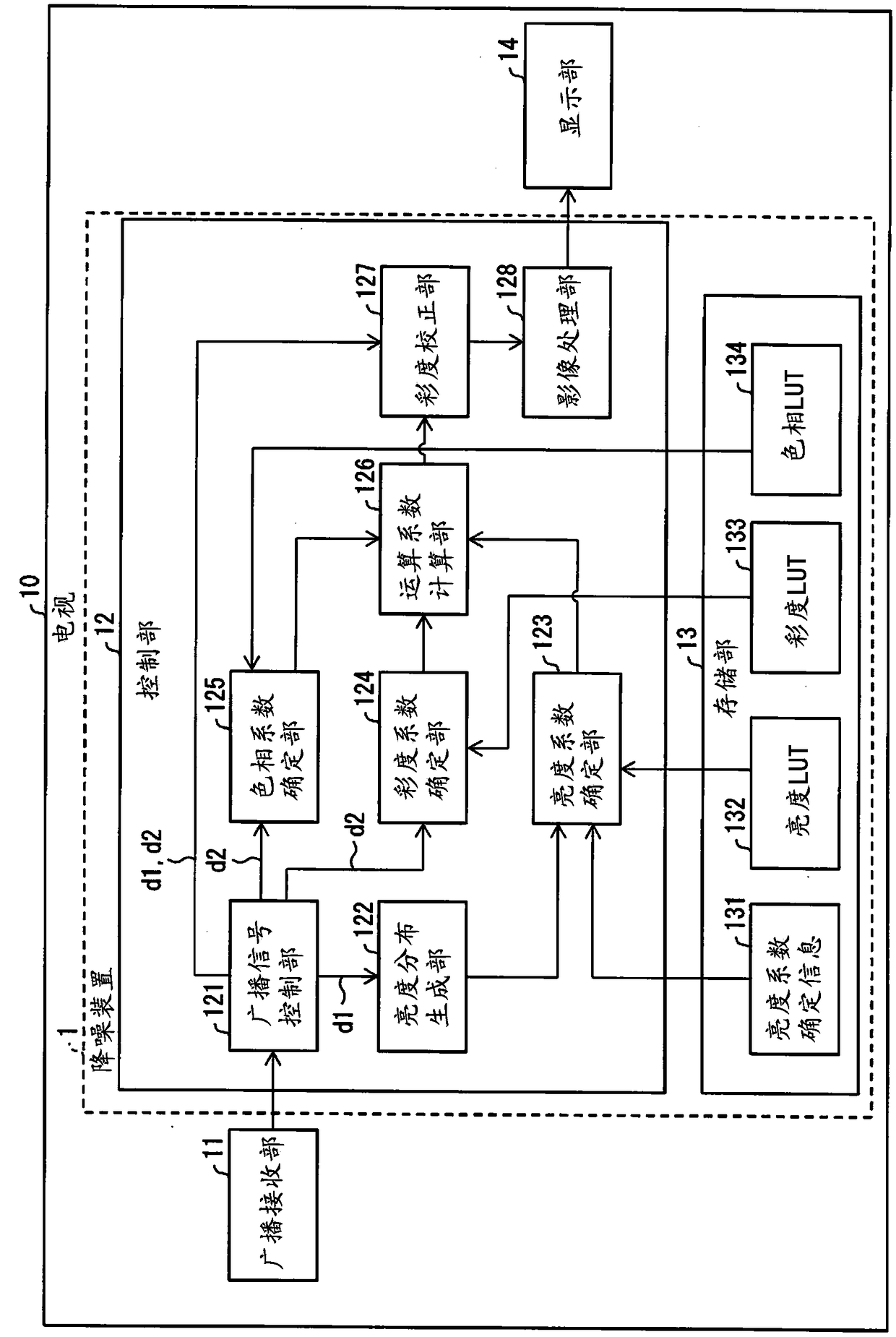
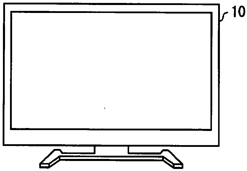
[0032] First, based on figure 1 and figure 2 The summary of the present invention will be described. figure 1 It is a block diagram showing an example of the configuration of main parts of a television 10 equipped with the noise reduction device 1 (display control device) according to this embodiment, figure 2 It is an external view showing an example of the external appearance of the television 10 (display device, TV receiver).
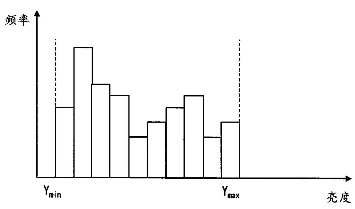
[0033] figure 1 The illustrated noise reduction device 1 controls the display of images on a television 10 . Specifically, the noise reduction device 1 reduces the color noise of the image displayed on the television 10. More specifically, the noise reduction device 1 determines, among still images (hereinafter, referred to as frames) constituting video content (for example, a r...
no. 2 approach 〕
[0083] based on Figure 10 and Figure 11 Descriptions of other embodiments of the present invention are as described above. In addition, in the following embodiments, for convenience of description, members having the same functions as those described in the above-mentioned embodiments are assigned the same reference numerals, and descriptions thereof are omitted.
[0084] Figure 10 It is a block diagram showing an example of the main part configuration of the television 10a according to this embodiment. When the TV 10a (in other words, the noise reduction device 1a mounted on the TV 10a ) uses an HDR (High Dynamic Range) signal indicating the maximum brightness (content The maximum brightness information (Maximum Content Light Level), and the appropriate low brightness range is defined as the frame of each content. Next, the details thereof will be described.
[0085] Such as Figure 10 As shown, the television 10a includes a control unit 12a instead of the control un...
no. 3 approach 〕
[0100] based on Figure 12 to Figure 14 Still another embodiment of the present invention will be described as follows.
[0101] Figure 12 It is a block diagram showing an example of the main part configuration of the television 10b according to this embodiment. The TV 10b (in other words, the noise reduction device 1b mounted on the TV 10b) corrects low brightness based on an input signal (in other words, based on user operation) input by the user using a remote controller (hereinafter, referred to as the remote controller 20 ) of the TV 10b or the like. Range determination coefficient B, operation coefficient A T . Next, the details thereof will be described.
[0102] Such as Figure 12 As shown, the television 10b includes a control unit 12b instead of the control unit 12. In addition, the television 10b newly includes a remote control receiving unit 15 for receiving a signal transmitted from the remote control 20 (hereinafter, referred to as a remote control signal)...
PUM
 Abstract
Description
Claims
Application Information
 - R&D
- Intellectual Property
- Life Sciences
- Materials
- Tech Scout
- Unparalleled Data Quality
- Higher Quality Content
- 60% Fewer Hallucinations
Browse by: Latest US Patents, China's latest patents, Technical Efficacy Thesaurus, Application Domain, Technology Topic, Popular Technical Reports.
© 2025 PatSnap. All rights reserved.Legal|Privacy policy|Modern Slavery Act Transparency Statement|Sitemap|About US| Contact US: help@patsnap.com


