Suspension arm for vehicle wheel suspension unit

A technology of wheel suspension and suspension arm, applied in the field of suspension arm, can solve the problems of increasing production cost and installation workload

Active Publication Date: 2018-12-25
FORD GLOBAL TECH LLC
View PDF10 Cites 0 Cited by
  • Summary
  • Abstract
  • Description
  • Claims
  • Application Information

AI Technical Summary

Problems solved by technology

However, if one intends to implement such different drive dynamics for a production series of vehicles, different suspension

Method used


Image

  • Suspension arm for vehicle wheel suspension unit
  • Suspension arm for vehicle wheel suspension unit
  • Suspension arm for vehicle wheel suspension unit

Examples


Embodiment Construction

[0027] In the various figures, parts of the same function are always provided with the same reference numerals, so that they are usually only described once.

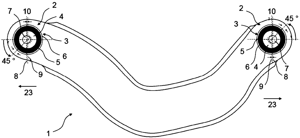
[0028] figure 1 A side view of an exemplary embodiment of a suspension arm 1 according to the invention is shown. figure 1The control arm 1 shown in is an arcuate arm of a wheel suspension unit of a motor vehicle (not shown), also not shown in detail. The arcuate arms are used in a manner known per se to fix the camber of the wheel attached to the wheel suspension unit. from figure 1 As can be seen in FIG. 1 , the control arm 1 has a substantially rod-shaped design, and bearing receptacles 2 for receiving rubber bearings 3 are respectively arranged on two opposite ends of the control arm 1 .

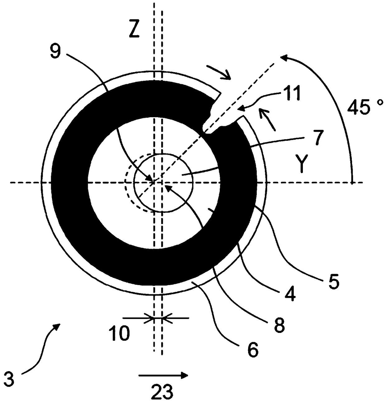
[0029] exist figure 2 , enlarged side view showing press-in figure 1 Rubber bearings 3 in the two bearing receptacles 2 of the control arm 1. especially, figure 2 The rubber bearing 3 in is shown in a state of being remov...


PUM


Abstract

The invention relates to a suspension arm (1, 18) for a wheel suspension unit of a vehicle. The suspension arm (1, 18) comprises at least one bearing receptacle (2), rubber bearings (3, 12, 19) fixedly held in a bearing receptacle and having rubber elastic bushings (5, 13, 20) fixedly surrounding the inner sleeves (4, 15, 21); the inner sleeves (4, 15, 21) include fastening holes (7, 16, 22). Thefastening holes (7, 16, 22) are arranged relative to the bearing receptacle (2) such that the central axes (8) of the fastening holes (7, 16, 22) have an offset (10) relative to the central axis (9) of the bearing receptacle (2).

Description

technical field [0001] The invention relates to a suspension arm for a wheel suspension unit of a vehicle, in particular a motor vehicle, according to the preamble of claim 1, the suspension arm comprising at least one bearing receptacle, fixedly held on Rubber bearing in the bearing receptacle with a rubber-elastic bushing fixedly surrounding an inner sleeve, wherein the inner sleeve contains fastening holes. Background technique [0002] By using common wheel suspension components such as suspension arms, wheel carriers, brackets, etc., the development of a vehicle platform representing the technical basis for constructing externally different vehicle models reduces the amount of effort needed, for example, to realize different driving dynamics in specific vehicle models. Selection of specific changes or adaptations to the wheel suspension unit for the vehicle. However, if it is intended to implement such different drive dynamics for a production series of vehicles, diffe...

Claims


Application Information

Patent Timeline
IPC IPC(8): B60G7/00B60G3/20
CPCB60G3/20B60G7/001B60G2204/422B60G2204/143B60G2204/41B60G2204/4103B60G2206/11B60G2206/91
Inventor 埃里克·伦纳德·布兰格安德列斯·卡利茨延斯·特辛法比奥·缪拉
Owner FORD GLOBAL TECH LLC
Why Eureka
Try Eureka