Rotating device of feeding machine of brake pump gland
A technology of rotating device and brake pump, which is applied to conveyor objects, transportation and packaging, etc., can solve problems such as low work efficiency and complex structure, and achieve the effect of reducing production costs and technical requirements.
- Summary
- Abstract
- Description
- Claims
- Application Information
AI Technical Summary
Problems solved by technology
Method used
Image

Examples
Embodiment Construction
[0011] The preferred embodiments of the present invention will be described in detail below in conjunction with the accompanying drawings, so that the advantages and features of the invention can be more easily understood by those skilled in the art, so as to define the protection scope of the present invention more clearly.
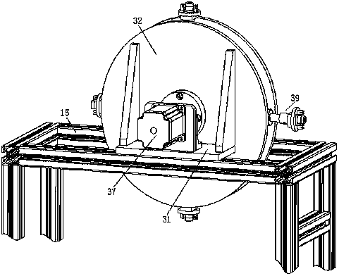
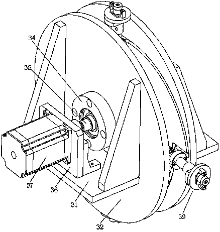
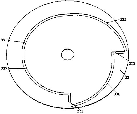
[0012] see Figure 1 to Figure 4 , the embodiment of the present invention includes:
[0013] A rotary device of a brake pump gland feeder, the rotary device of the brake pump gland feeder includes a frame 15 fixed on the ground, and two parallel backing plates 31 are fixed on the frame 15. All are fixed with disc 32 by reinforcing rib on the backing plate 31, two discs 32 are concentric, leave gap between two discs 32 and are all positioned between two backing plates 31, two discs 32 A guide slideway 33 is provided on the opposite inner side, and two guide slideways 33 are arranged symmetrically. Three guide slideways 332, the fourth guide slideway 33...
PUM
 Abstract
Description
Claims
Application Information
 - R&D
- Intellectual Property
- Life Sciences
- Materials
- Tech Scout
- Unparalleled Data Quality
- Higher Quality Content
- 60% Fewer Hallucinations
Browse by: Latest US Patents, China's latest patents, Technical Efficacy Thesaurus, Application Domain, Technology Topic, Popular Technical Reports.
© 2025 PatSnap. All rights reserved.Legal|Privacy policy|Modern Slavery Act Transparency Statement|Sitemap|About US| Contact US: help@patsnap.com