Fixing seat for computer display screen

A display screen and computer technology, applied in the computer field, can solve the problems of poor applicability, small adjustment angle, inconvenient adjustment method, etc., and achieve the effect of increasing convenience and applicability

Active Publication Date: 2018-12-25
滁州市皖东规划建筑勘察设计研究院
View PDF8 Cites 4 Cited by
  • Summary
  • Abstract
  • Description
  • Claims
  • Application Information

AI Technical Summary

Problems solved by technology

[0003] The purpose of the present invention is to provide a fixing seat for a computer display screen to solve the problems in the above-mentioned background technology that the d

Method used


Image

  • Fixing seat for computer display screen
  • Fixing seat for computer display screen
  • Fixing seat for computer display screen

Examples


Embodiment 1

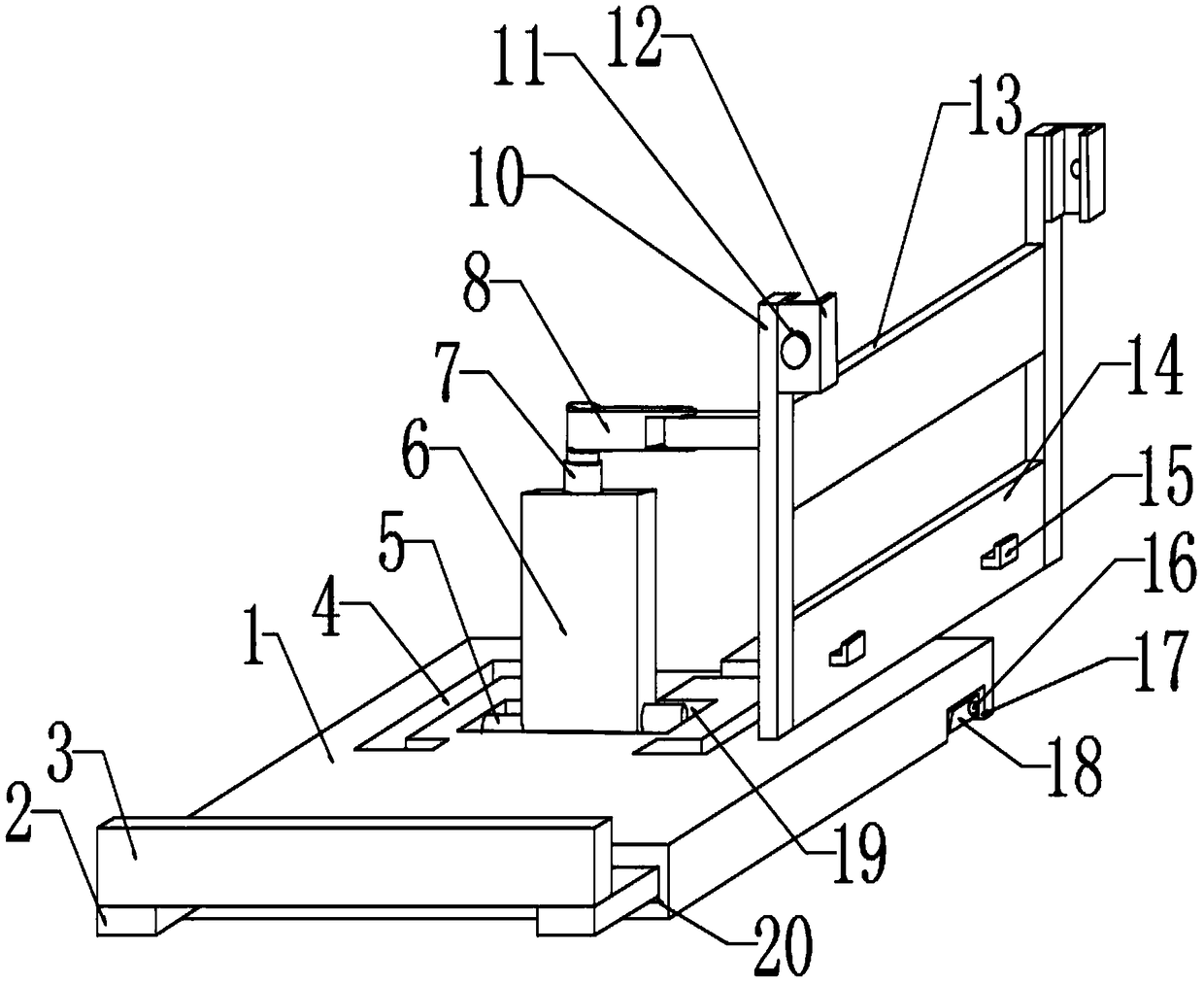
[0022] see Figure 1-5 , the present embodiment provides a fixing seat for a computer display screen, comprising a base 1, two first grooves 20 are arranged on both sides of the base 1, and a movable rod 2 is snapped into the two first grooves 20 respectively, and the two One end of each movable rod 2 away from the first groove 20 is fixedly installed with a limit bar 3, and the end of the base 1 both sides away from the limit bar 3 is provided with a second groove 17, and the second groove 17 is rotationally connected by the first rotating shaft 16. There are support feet 18, a T-shaped slot 19 is provided in the middle of the upper surface of the base 1, and a groove is provided at the bottom of the T-shaped slot 19. The base 1 on both sides of the T-shaped slot 19 is provided with counterweight mounting slots 4, T-shaped slots 19 The second rotating shaft 5 is connected to the inner rotation, and the second rotating shaft 5 is fixedly connected to the support block 6, and t...

Embodiment 2

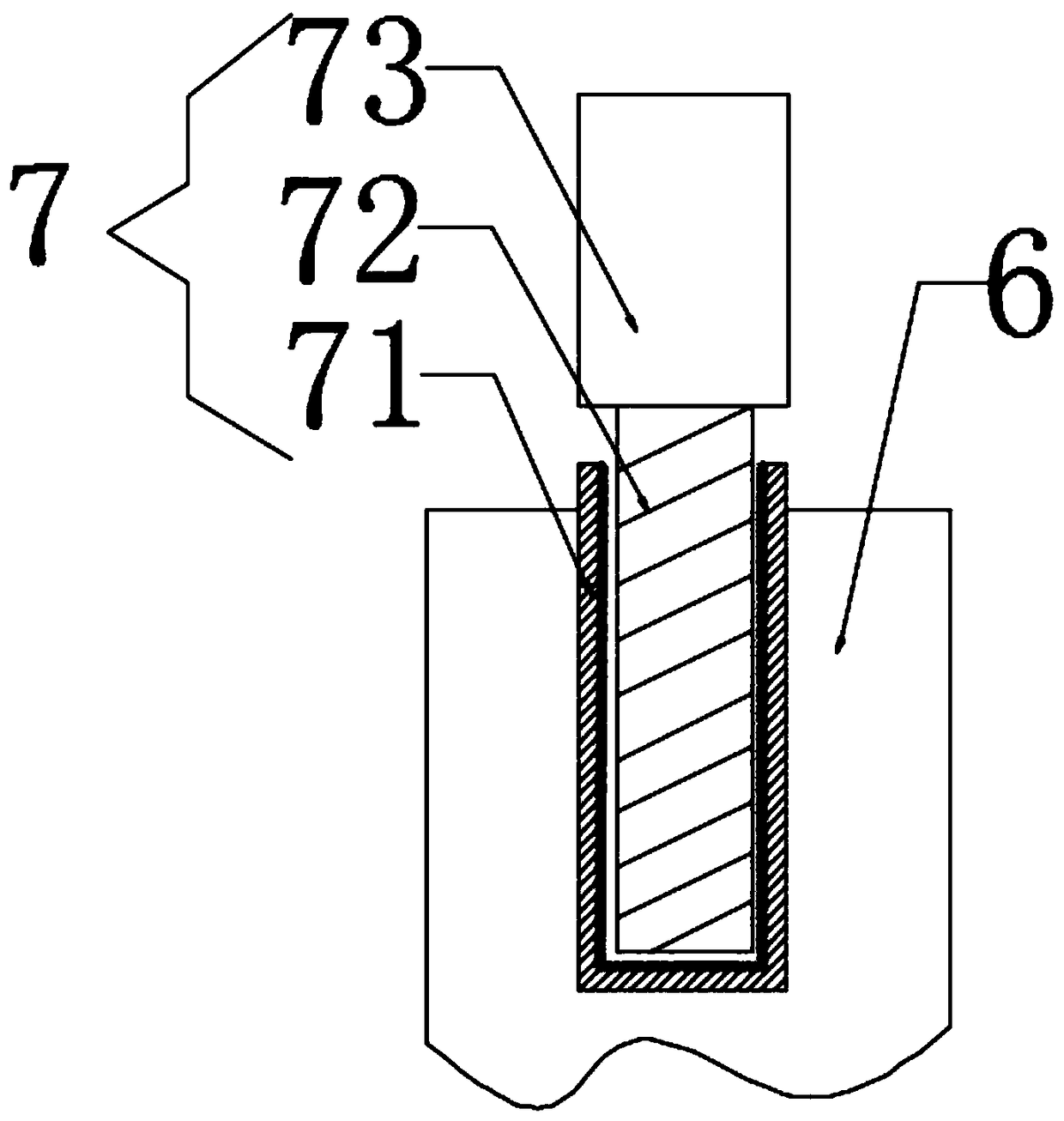
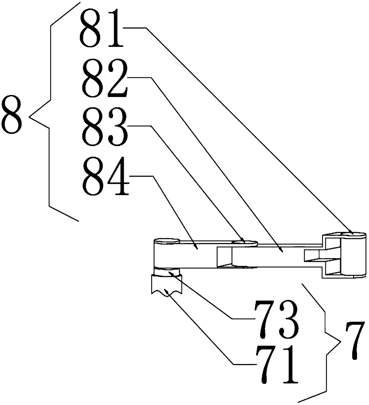
[0025] see Figure 2-3 , On the basis of Embodiment 1, a further improvement has been made: the threaded telescopic rod 7 includes a threaded rod sleeve 71, a threaded rod 72 and a turning handle 73, the threaded rod sleeve 71 is fixedly installed in the inner groove of the support block 6, and the turning handle 73 is fixed Installed on one end of the threaded rod 72, the threaded rod 72 is rotatably connected with the threaded rod sleeve 71 by threads, the inner wall of the threaded rod sleeve 71 is provided with the same thread as the threaded rod 72, and the adjusting rod 8 includes a fourth rotating shaft 81, a second support rod 82 , the fifth rotating shaft 83, and the first support rod 84, one end of the second supporting rod 82 is rotatably connected with the fourth rotating shaft 81, and the end of the second supporting rod 82 away from the fourth rotating shaft 81 is fixedly connected with the fifth rotating shaft 83, the first The support rod 84 is rotatably connec...


PUM


Abstract

The invention discloses a fixing seat for a computer display screen. The fixing seat comprises a base, wherein two first grooves are formed in two sides of the base; movable rods are respectively clamped in the two first grooves; the ends, away from the first grooves, of the two movable rods are fixedly provided with limiting strips; a T-shaped slot is formed in the middle part of the upper surface of the base; a second rotating shaft is connected into the T-shaped slot in a rotatable manner; the second rotating shaft is fixedly connected with a supporting block; the supporting block is fixedly connected with a threaded telescopic rod through a groove in the supporting block; the end, away from the supporting block, of the threaded telescopic rod is fixedly connected with an adjustment rod; the end, away from the threaded telescopic rod, of the adjustment rod is connected with a connection block in a rotatable manner; the connection block is fixedly connected with a first supporting plate; and a carrying block is fixedly mounted on the outer side of a second supporting plate. According to the fixing seat for the computer display screen, a distance between a person and the display screen can be easily adjusted, and an adjustable angle is increased; and the fixing seat also can be used as a notebook computer mat, so the applicability is improved.

Description

technical field [0001] The invention relates to the technical field of computers, in particular to a fixing base for computer display screens. Background technique [0002] The computer is one of the greatest scientific and technological inventions of the 20th century. In various fields of industry, agriculture, and human society, many major breakthroughs have been made in the application of computers. Even the weather forecasts we listen to and watch every day are inseparable from the scientific calculations of computers. With the advancement of science and technology, the rapid development of various computer technologies and network technologies, the development of computers has entered a fast and new era. Computers have developed from single functions and large volumes to complex functions, small volumes, and resource networks. The traditional display base has a single function, although it has the function of freely adjusting the angle, but when adjusting, because it i...

Claims


Application Information

Patent Timeline
IPC IPC(8): F16M11/04F16M11/26
CPCF16M11/043F16M11/26
Inventor 曹结宾
Owner 滁州市皖东规划建筑勘察设计研究院
Why Eureka
Try Eureka