

Uniformity degree controllable stirrer used in laboratory
A uniformity, mixer technology, applied in mixer accessories, mixers with rotating mixing devices, mixers, etc., can solve the problems of inability to achieve mixing and inability to meet real-time control of the material to be mixed, and achieve good use effect and uniformity. degree of controllable effect
Inactive Publication Date: 2018-12-28
自贡莱德曼科技有限公司
View PDF1 Cites 9 Cited by
- Summary
- Abstract
- Description
- Claims
- Application Information
AI Technical Summary
Problems solved by technology
However, the above-mentioned laboratory mixer cannot satisfy the real-time control of the material to be stirred inside the mixer during use, and cannot realize the materials in the mixer to be stirred out in different situations. Materials with different degrees of uniformity required in different situations
Method used
View moreImage
Smart ImageViewing Examples

Examples
Embodiment 1
Embodiment 2
Embodiment 3
Login to View More PUM
 Abstract
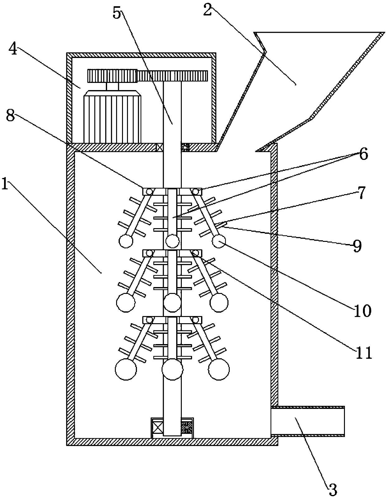
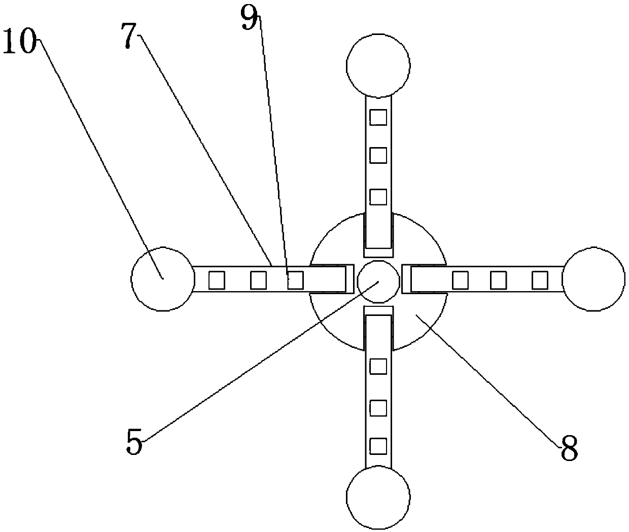
The invention discloses a uniformity degree controllable stirrer used in a laboratory, belongs to the technical field of laboratory equipment, and aims to provide a stirrer capable of stirring materials of different uniformity degrees. According to the technical scheme, the stirrer comprises a stirring tank body, a feeding hopper and a discharge tube, wherein the feeding hopper is arranged at theupper end of the stirring tank body, the feeding copper communicates with the interior of the tank body, the discharge tube is arranged at the lower end of the stirring tank body, and the discharge tube communicates with the interior of the stirring tank body; a power box is fixedly arranged at the upper end of the tank body; a stirring main shaft is arranged on the stirring tank body; the upper end of the stirring main shaft penetrates through the upper end of the power box; the upper end of the stirring main shaft is placed in the power box; a centrifugal stirring component is arranged at apart, placed inside the stirring tank body, of the stirring main shaft; a centrifugal moveable stirring rod is arranged in the centrifugal stirring component; and the centrifugal moveable stirring rodis hinged with the stirring main shaft. The invention provides the uniformity degree controllable stirrer, and materials of different uniformity degrees can be stirred.
Description
technical field The invention belongs to the technical field of laboratory equipment, and in particular relates to a mixer with controllable uniformity used in laboratories. Background technique The stirrer is a kind of equipment commonly used in the laboratory. The stirrer generally includes a vertical container body and a stirring device; the stirring device includes a stirring shaft and a stirring paddle. The stirring paddle is installed on the stirring shaft, and the stirring shaft is mainly driven by a motor to stir the solution. Make it evenly distributed. Application number CN201721038368.2 discloses a laboratory mixer. The mixer includes a shell and a stirring shaft installed in the shell, the stirring shaft is driven by a driving device, the shell is provided with a shell cover above the shell, a circular guide rail is arranged on the shell cover, and the stirring The shaft is installed in the guide rail, and driven by the second driving device to move on the gui...
Claims
Login to View More Application Information
Patent Timeline
 Patent Type & AuthorityApplications(China)
IPC IPC(8): B01F7/16B01F15/00
CPCB01F27/0542B01F27/0722B01F27/0723B01F27/111B01F27/192B01F27/80B01F35/221422B01F2101/23
Inventor何翠英
Owner自贡莱德曼科技有限公司