Centrifugal machine balancing device based on position adjustment of rotation center, and method

A technology of slewing center and centrifuge, applied in the field of centrifuge

Pending Publication Date: 2018-12-28
GENERAL ENG RES INST CHINA ACAD OF ENG PHYSICS
View PDF11 Cites 7 Cited by
  • Summary
  • Abstract
  • Description
  • Claims
  • Application Information

AI Technical Summary

Problems solved by technology

Since the trim range and the driving force required for trim are mutually restricted, this trim method is only applicable to large-range static trim or small-range dynamic trim

Method used


Image

  • Centrifugal machine balancing device based on position adjustment of rotation center, and method
  • Centrifugal machine balancing device based on position adjustment of rotation center, and method
  • Centrifugal machine balancing device based on position adjustment of rotation center, and method

Examples


Embodiment Construction

[0041] The present invention will be further described below in conjunction with accompanying drawing:

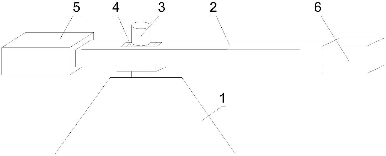
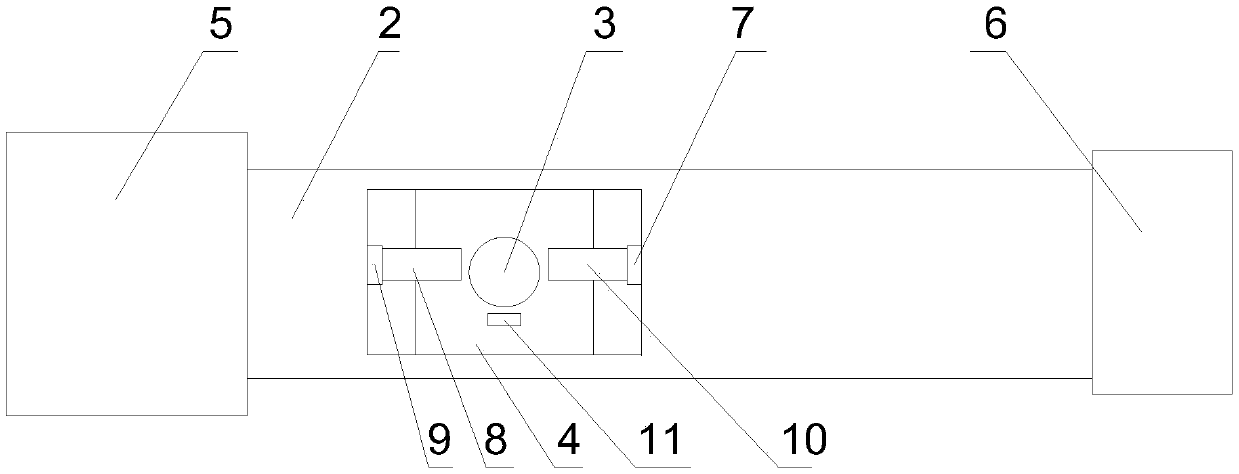
[0042] like figure 1 and figure 2 As shown, a centrifuge balance device based on the position adjustment of the center of rotation of the present invention includes a rotating arm 2, a rotating arm support 4, a motion guiding mechanism, a fixed counterweight 5 and a test piece 6, and the centrifuge rotating arm is installed on the base 1 Above, the rotating arm support 4 is fixedly connected with the centrifuge shaft 3, and the rotating arm support 4 is fixedly connected with the rotating arm 2 through the motion guiding mechanism. At both ends of the rotating arm 2, a rectangular through slot is arranged on the rotating arm 2, and the rotating arm support 4 is arranged in the rectangular through slot. 4 slide left and right;

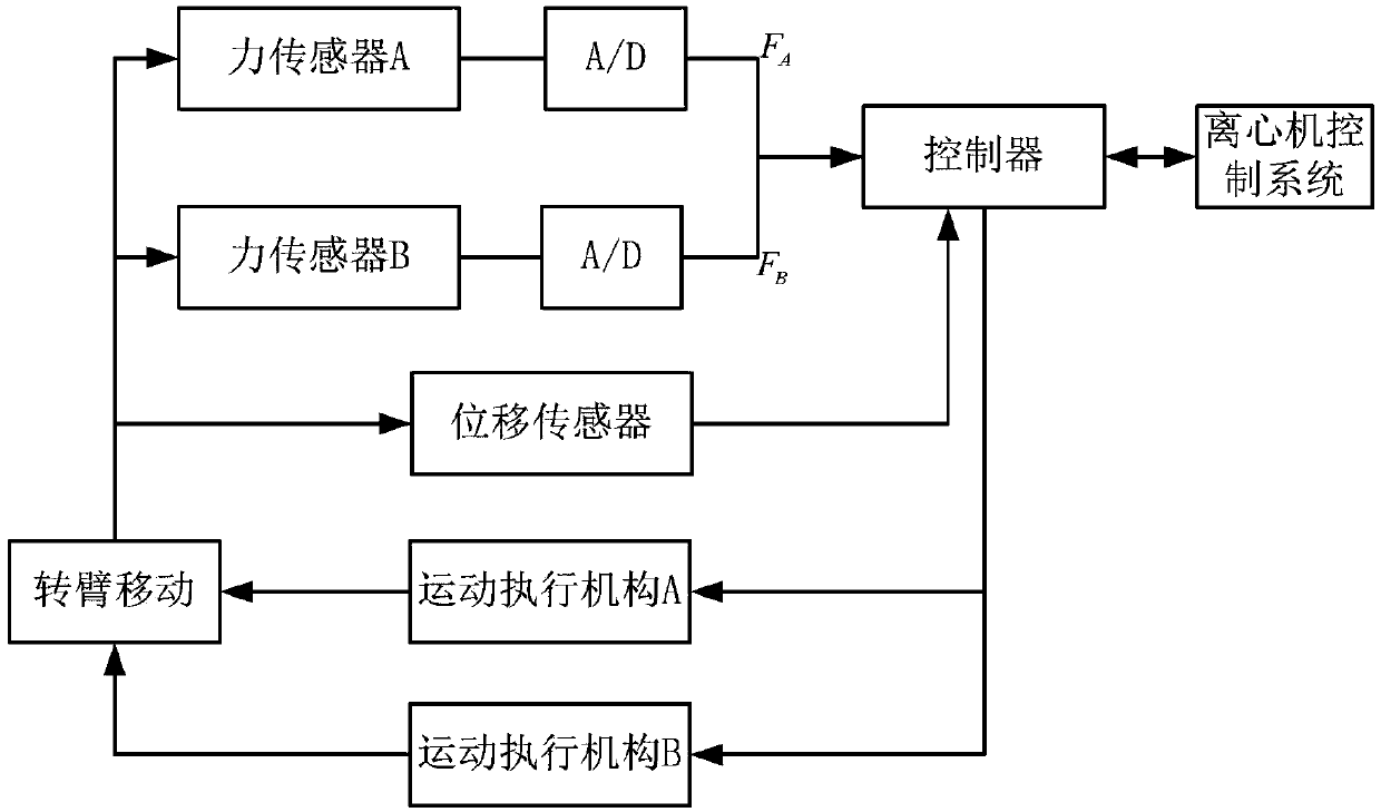
[0043]The motion guiding mechanism includes a controller, a motion actuator A 8, a motion actuator B 10, a force sensor A 9, a force sensor B 7 ...


PUM


Abstract

The invention discloses a centrifugal machine balancing device based on position adjustment of the rotation center. The centrifugal machine balancing device comprises a rotating arm, a rotating arm support, a motion guiding mechanism, a fixed counterweight and a test piece. The rotating arm support is fixedly connected with a rotating shaft of a centrifugal machine and fixedly connected with the rotating arm through the motion guiding mechanism. The fixed counterweight and the test piece are arranged at the two ends of the rotating arm correspondingly. A dynamic balancing method comprises thesteps that the values of FA and FB are judged, if FA is greater than FB, a motion executing mechanism A is elongated, a motion executing mechanism B is shortened synchronously, otherwise, the motion executing mechanism B is elongated, and the motion executing mechanism A is shortened synchronously; and the rotating speed of the centrifugal machine is changed, and the test piece end of the centrifugal machine is subjected to acceleration compensation. According to the centrifugal machine balancing device, by controlling the rotating arm to move relative to the rotating arm support under restraint of the motion guiding mechanism, adjustment of the rotation center is completed; and the real-time balancing method is adopted, when unbalanced force is gradually increased with increasing of the rotating speed, a balancing system also adjusts the position of the rotating arm synchronously, and thus dynamic balancing can be achieved in the full rotating speed range of the centrifugal machine.

Description

technical field [0001] The invention relates to a centrifuge, in particular to a centrifuge trimming device and method based on the position adjustment of the center of rotation. Background technique [0002] The centrifuge for scientific experiments is a device that uses the rotating parts to rotate around the shaft to provide an overload environment; in order to ensure the stable operation of the centrifuge, the center of mass of the rotating parts must coincide with the center of rotation, and the center of mass of the rotating parts is affected by the centrifuge specimen. Therefore, each test It is necessary to adjust the rotating parts according to the condition of the test piece. This adjustment process is called the trimming of the centrifuge. The trimming of the centrifuge is the basis for ensuring the stable, safe and long-life operation of the centrifuge. Excessive unbalanced force may lead to major accidents. [0003] At present, all centrifuges are equipped with ...

Claims


Application Information

Patent Timeline
Patent Type & Authority Applications(China)
IPC IPC(8): B04B9/14
CPCB04B9/14B04B9/146
Inventor 白俊林宋琼舒杨陈文颖冉光斌罗龙
Owner GENERAL ENG RES INST CHINA ACAD OF ENG PHYSICS
Why Eureka
Try Eureka