
Automatic frame bar assembling machine

A framing machine and automatic technology, which is applied in the jointing of wooden veneers, wood processing equipment, manufacturing tools, etc., can solve problems such as poor splicing and splicing effects between interfaces, and the inability to apply automatic assembly of frame strips, etc., to achieve Good versatility, guaranteed splicing effect

Pending Publication Date: 2018-12-28
苏州春巽动力机械设备有限公司
View PDF9 Cites 1 Cited by
  • Summary
  • Abstract
  • Description
  • Claims
  • Application Information

AI Technical Summary

Problems solved by technology

[0003] However, this assembly method is relatively light in weight for wooden frame bars. When pushed away from the bottom of a group of frame bars that are stacked together, there may be a slight jump, resulting in a There is a situation where splicing cannot be spliced ​​or the splicing effect is not good between the middle interface
And for the frame bar whose upper surface is inclined (such as Figure 4 As shown), the vertical stacking of the frame strips cannot be completed before assembly, so the existing frame machine cannot be applied to the automatic assembly of such frame strips

Method used


Image

  • Automatic frame bar assembling machine
  • Automatic frame bar assembling machine
  • Automatic frame bar assembling machine

Examples


Embodiment Construction

[0020] The present invention will be further described below in conjunction with the accompanying drawings.

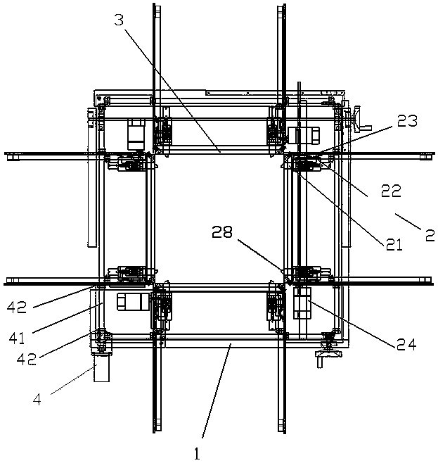
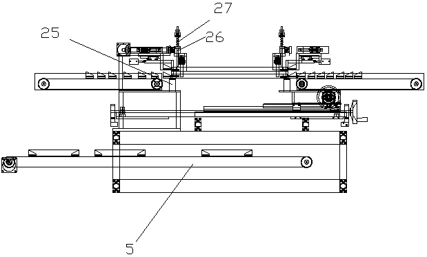
[0021] Such as Figure 1-Figure 5 As shown, an automatic framing machine includes a machine platform 1, four sets of feeding conveyor belts 2 are arranged on the machine platform 1, and the angle between two adjacent groups of feeding conveyor belts 2 is 90°, Both sides of the end of the feeding conveyor belt 2 are provided with mechanical grippers 21 for grasping the frame strips 3, and a jacking device 25 for jacking up the frame strips 3 is arranged below the mechanical grippers 21. One side of the mechanical gripper 21 is provided with a frame bar reference positioning rod 26 with the same height of spliced ​​tenons, and the mechanical grippers 21 at least two groups of feeding conveyor belts 2 ends in the four groups of feeding conveyor belts 2 can move toward the The center direction of machine table 1 moves.

[0022] Place the frame strips that need to be spli...


PUM


Abstract

The invention discloses an automatic frame bar assembling machine, which comprises a machine platform. Four groups of feeding conveyor belts are arranged on the machine platform, and the angle betweentwo adjacent groups of feeding conveyor belts is 90 degrees. The both sides of the ends of the feeding conveyor belts are provided with mechanical graspers for grasping frame bars, a jacking device for jacking the frame bars is arranged under each mechanical grasper, one side of each mechanical grasper is provided with a frame bar reference positioning rod with a consistent splicing tenon surfaceheight, and the mechanical graspers at the ends of at least two groups of the feeding conveyor belts in the plurality of feeding conveyor belts can move towards the center direction of the machine platform. The frame bars in place are jacked by the jacking devices, and the frame bars are positioned at the same height by the frame bar reference positioning rods. Then the frame bars are grasped bythe mechanical graspers. Finally, by synchronously pushing the mechanical grippers to move toward the center direction, the frame splicing is completed.

Description

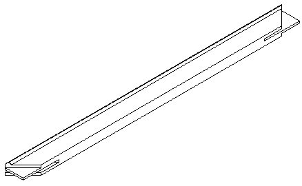
technical field [0001] The invention relates to an automatic framing machine, which belongs to the technical field of automation equipment. Background technique [0002] In the existing automatic framing machine, the frame strips corresponding to the four sides are usually placed on the frame machine in a vertically superimposed manner to form a directional structure. There is a certain gap between two adjacent sets of frame strips. During the process, it is assembled by pushing the four frame bars at the bottom at the same time. [0003] However, this assembly method is relatively light in weight for wooden frame bars. When pushed away from the bottom of a group of frame bars that are stacked together, there may be a slight jump, resulting in a There is a situation that the middle interface cannot be spliced ​​or the splicing effect is not good. And for the frame bar whose upper surface is inclined (such as Figure 4 shown), the vertical stacking of the frame strips canno...

Claims


Application Information

Patent Timeline
Patent Type & Authority Applications(China)
IPC IPC(8): B27D1/10
CPCB27D1/10
Inventor 钟志强钟国斌
Owner 苏州春巽动力机械设备有限公司
Learn More