Automatic jigsaw machine with beam adjustment function

An automatic jigsaw machine and beam technology, applied in the direction of manufacturing tools, wood processing equipment, wooden veneer joints, etc., can solve the problem of poor splicing effect, unfavorable energy consumption of the pushing plate action cylinder, and the overall movement effect of the pushing plate difficult to guarantee

Inactive Publication Date: 2016-09-07
韩莉 +7
View PDF10 Cites 0 Cited by
  • Summary
  • Abstract
  • Description
  • Claims
  • Application Information

AI Technical Summary

Problems solved by technology

Although this patent solution can realize the technical effect of the penultimate 6th line to the penultimate line 3rd line on the first page of the instruction manual, since the pushing mechanism only consists of a pair of pushing plate action cylinders (patent optional oil cylinders) and a The pusher plate of the plate action cylinder is composed of a pusher plate connected to the end of the cylinder column, so in the actual use process, the pusher mechanism will inevitably produce the following technical problems: First, because the pusher plate is relatively lengthy (usually larger than equal to 122㎝), and because the middle part of the length direction of the pusher plate facing the side of the pusher plate action cylinder is connected to the end of the pusher plate action cylinder column, the cylinder column protrudes out of the cylinder when the push plate action When driving the pusher plate to move, the pusher plate behaves as a negative movement, that is, a passive movement. It is difficult to guarantee the overall movement effect of the pusher plate, that is to say, it is difficult to ensure the overall synchronous movement of the two ends and the middle of the entire pusher plate. effect, which affects the balanced pushing effect of the sheet material entering the sheet material cavity on the frame; secondly, because the pusher plate is directly placed on the pusher plate platform of the frame, the frictional resistance is large, which is not conducive to saving push. The energy consumption of the plate acting on the cylinder, and the frequent friction between the pushing plate and the pushing plate platform of the frame will damage the pushing plate; third, because only one heating mechanism heats the upper part of the plate, it is not conducive to ensuring The overall bonding effect between the adjacent panels of the panel splicing, because heating the panel on one side will cause the panel to be heated to produce a yin and yang situation. Specifically, the side facing the heating mechanism can obtain the desired heating effect, while the side away from The plate on one side of the heating mechanism is not heated enough; Fourth, because it realizes the overall lifting of the workbench through the roller mechanisms arranged at both ends of the workbench, that is, the overall lift of the workbench responds to changes in the thickness of the plate, and drives The lifting device of the roller mechanism is composed of a motor, a reducer, a screw, a push plate and a guide rail slide plate, etc., so the overall structure is relatively complicated
In addition, because this patent can only heat the upper part of the slats, the splicing effect will be inferior to that of the aforementioned CN2265880Y, and there are also some defects described in CN2265880Y

Method used


Image

  • Automatic jigsaw machine with beam adjustment function
  • Automatic jigsaw machine with beam adjustment function
  • Automatic jigsaw machine with beam adjustment function

Examples


Embodiment Construction

[0025] In order to facilitate a clearer understanding of the technical essence and beneficial effects of the present invention, the applicant will describe in detail the following in the form of examples, but the description of the examples is not a limitation to the solution of the present invention. All equivalent transformations that are merely formal but not substantive should be regarded as the scope of the technical solution of the present invention.

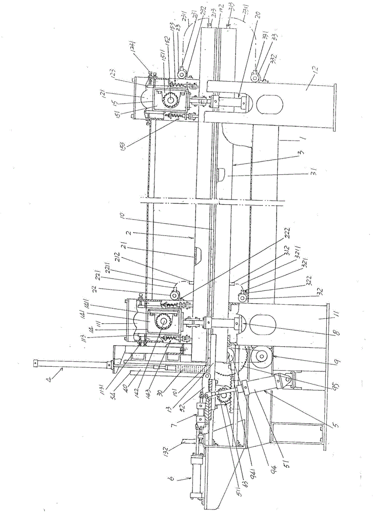
[0026] In the following descriptions, all concepts involving up, down, left, right, front and back are for figure 1 As far as the positional state shown is concerned, it should not be understood as a special limitation of the present invention.

[0027] See figure 1 , a frame 1 is given, the left end of the frame 1 is fixed between a pair of frame left columns 11 that are set facing each other and are supported on the floor in the state of use in a state vacated on the floor, and The right end of frame 1 is also fixed be...


PUM


Abstract

The invention provides an automatic board splicing machine with a crossbeam adjustment function and belongs to the technical field of woodworking machines. The automatic board splicing machine comprises a machine frame, an upper heating mechanism, a lower heating mechanism, a board pressing mechanism, a turning mechanism and a pushing mechanism, wherein the pushing mechanism comprises a pair of pushing plate actuation cylinders, a pushing plate and a pair of pushing plate synchronization devices; the upper heating mechanism comprises a set of upper heating pipes, an upper heating pipe heating medium lead-in header pipe and an upper heating pipe heating medium lead-out header pipe; the lower heating mechanism comprises a set of lower heating pipes, a lower heating pipe heating medium lead-in header pipe and a lower heating pipe heating medium lead-out header pipe; a board row moving channel is formed between the upper heating pipes and the lower heating pipes; the board pressing mechanism is fixed to the upper heating pipes; opposite sides of a pair of left machine frame stand columns are open, and opposite sides of a pair of right machine frame stand columns are open; a left adjustment crossbeam gear shaft is arranged in a left adjustment crossbeam chamber, and a right adjustment crossbeam gear shaft is arranged in a right adjustment crossbeam chamber; left adjustment crossbeam vertical adjustment mechanisms are arranged in a pair of left machine frame stand column chambers respectively, and right adjustment crossbeam vertical adjustment mechanisms are arranged in a pair of right machine frame stand column chambers respectively; each left adjustment crossbeam vertical adjustment mechanism comprises a lifting actuation cylinder, a ruler screw rod adjustment plate, a ruler screw rod, a ruler screw rod fixing plate, a synchronous adjustment rack and a gear.

Description

technical field [0001] The invention belongs to the technical field of wood processing machinery, and in particular relates to an automatic jigsaw machine with a beam adjustment function. Background technique [0002] The function of the jigsaw machine mentioned above is to splice the slats of different lengths but tend to be the same in thickness and width produced by wood product manufacturers in the process of producing wood products into such as 122 (width) × 244 (length) ) cm whole board, used as furniture, cabinets and interior decoration boards, its positive significance lies in the saving of precious wood resources. [0003] The technical information about the jigsaw machine can be seen in the published Chinese patent literature, such as the authorized announcement number CN2265880Y recommending a "heating jigsaw machine". Both ends of the heating tube are provided with support rods, and the heating tube is placed on the upper part of the frame (patent called the ba...

Claims


Application Information

Patent Timeline
Patent Type & Authority Patents(China)
IPC IPC(8): B27D1/10
CPCB27D1/10
Inventor 王震郭凤霞邱湘苏军永
Owner 韩莉
Why Eureka
Try Eureka