Shaft frame of aluminum alloy sightseeing elevator

A sightseeing elevator and aluminum alloy technology, which is applied to vertical pipes, building components, buildings, etc., can solve the problems of increasing installation work, unsightly appearance, and reducing the area of ​​single glass, so as to prevent random disassembly and movement, avoid The effect of collision interference

Pending Publication Date: 2018-12-28
浙江安家快速电梯有限公司
View PDF2 Cites 8 Cited by
  • Summary
  • Abstract
  • Description
  • Claims
  • Application Information

AI Technical Summary

Problems solved by technology

These hoistway frames in the prior art, except on-site or factory welding, the fixing bolts used for connection, all the hoistway wires and cables are all exposed, if it needs to be hidden, auxiliary facilities such as bridges and pipelines must be used. Of course, these The device is also mainly used for indoor semi-enclosed elevator installation shafts, without a glass installation scheme
At present, the glazing of the hoistway of the sightseeing elevator basically adopts traditional auxiliary moldings or fixed cement, etc., which not only needs to increase the amount of installation work, reduce the area of ​​​​a single glass, and can only be installed outside the hoistway. However, from the outside of the derrick, the crosspieces, diagonal bracing rods, columns, decorative strips, connectors, etc. can be seen at a glance, which is very unsightly

Method used


Image

  • Shaft frame of aluminum alloy sightseeing elevator
  • Shaft frame of aluminum alloy sightseeing elevator
  • Shaft frame of aluminum alloy sightseeing elevator

Examples


Embodiment 1

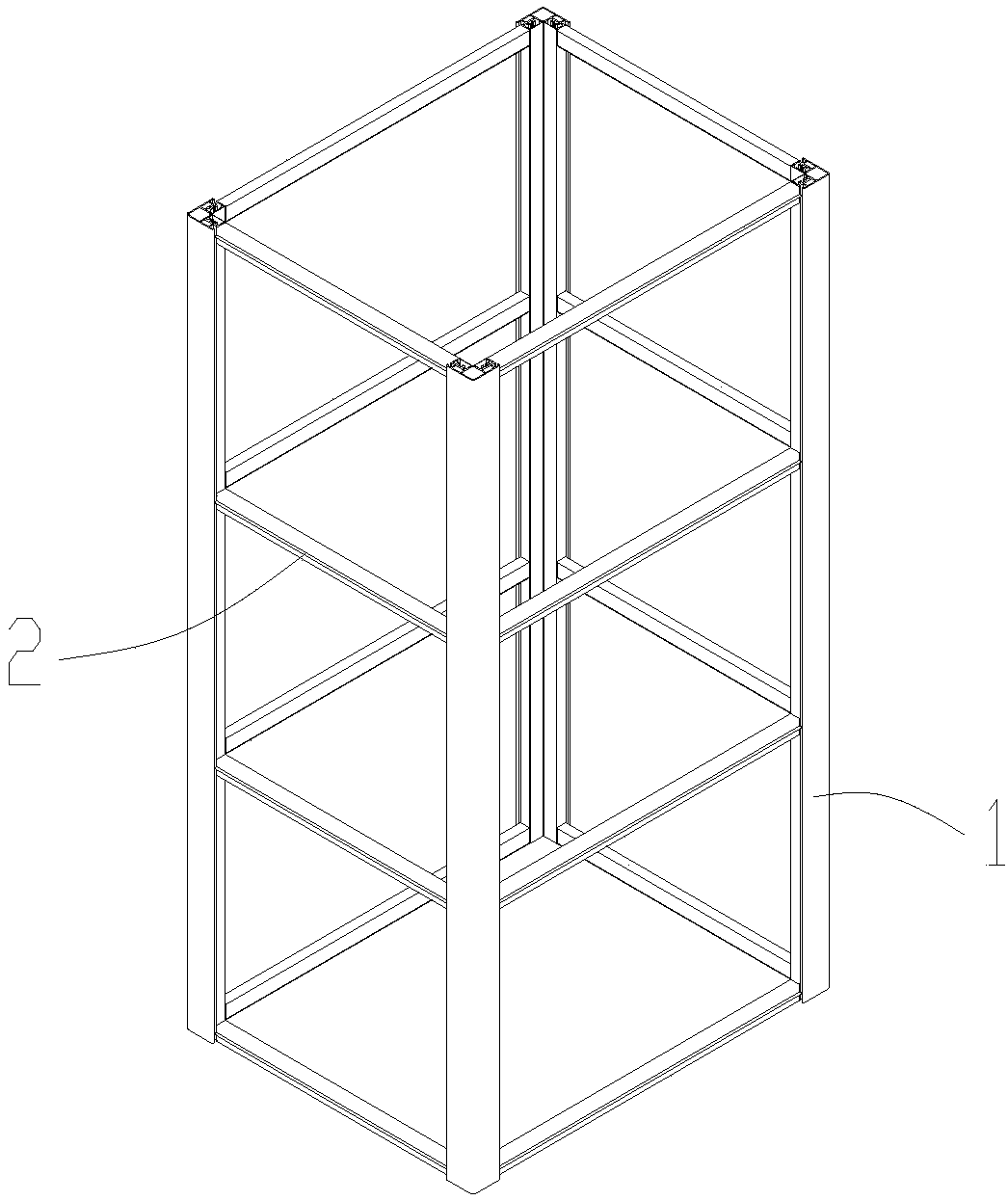
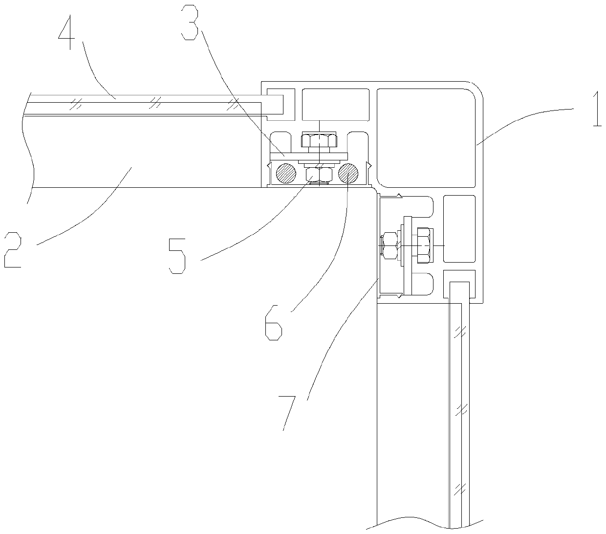
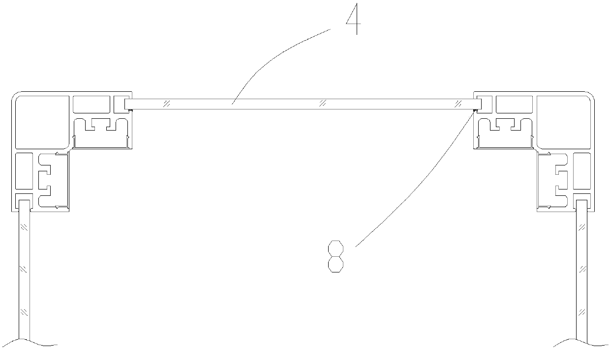
[0036] Embodiment one, such as figure 1 As shown, the application of the middle shaft: four columns 1 and 16 crosspieces 2 form a cuboid shaft. The column 1 and the crosspiece 2 are connected with each other by a T-shaped connecting plate 31 or a right-angled connecting plate 32 with fixing bolts 5 and nuts. And the hoistway cable 6 is arranged in the cable accommodation space 15 and the closed cable tray, and then the cover plate 7 is used to cover all the profile wiring areas. Install exterior glass 4 again, exterior glass 4 is positioned at the gap of crosspiece 2 glass partitions 21 positions up and down with glass glue filling.

Embodiment 2

[0037] Embodiment 2, the application of the entrance shaft: four upright columns 1 and 14 crosspieces 2 form a rectangular parallelepiped shaft. Wherein one side is retained as the gate, and the column 1 and the crosspiece 2 are connected by a T-shaped connecting plate 31 or a right-angled connecting plate 32 with fixing bolts 5 and nuts. And the hoistway cable 6 is arranged in the cable accommodation space 15 and the closed cable tray, and then the cover plate 7 is used to cover all the profile wiring areas. The exterior glass 4 is installed again, and the gap between the top and bottom of the exterior glass 4 and the glass spacer 21 of the crosspiece 2 is filled with glass glue. Install an integrated door cover at the door court.


PUM


Abstract

The invention discloses a shaft frame of an aluminum alloy sightseeing elevator. The shaft frame comprises vertical posts positioned at the rectangular corners and crosspieces connected between the corresponding vertical posts. The shaft frame is characterized in that every vertical post comprises a hollow main pipe, mounting wings are arranged in two mutually perpendicular directions by taking the hollow main pipe as a benchmark, every crosspiece are connected on one side of the corresponding mounting wing, a glass bezel is formed in every mounting wing on the outer side of the correspondingcrosspiece, a T-shaped slide groove is formed in the inner side of every mounting wing and is positioned in a cable holding space consisting of one side edge of the mounting wing and a vertical edge of the corresponding hollow main pipe, a cover plate is arranged on an opening of the cable holding space, the crosspieces are connected with the connecting plates arranged in the cable holding spaces,shaft cables are arranged in the cable holding spaces, and exterior decorating glass is assembled through the glass bezels. The shaft frame of the aluminum alloy sightseeing elevator has the advantages that mounting can be carried out inside and outside the shaft frame, all fixing parts and the cables are hidden in the holding spaces, and the exterior decorating glass is safe to assemble and elegant in appearance.

Description

technical field [0001] The invention relates to elevator technology, in particular to an aluminum alloy sightseeing elevator derrick. Background technique [0002] The main structure of the existing elevator derrick is roughly the same. For example, a kind of elevator derrick whose patent notification number is CN206156527U includes a door frame and a derrick. There is a chute on the crossbeam of the derrick, and the fixing buckle device includes a base. There are two L-shaped fixing buckles hinged on the base. When the two L-shaped fixing buckles are buckled together, a rectangular space is formed with the derrick. The opposite side of the fixing buckle is provided with a convex line matching the sliding groove, and the fixing buckle device is slidably connected in the sliding groove of the derrick beam through the convex line on the base. Another example is that the patent announcement number is CN207698959U, a kind of elevator derrick, including columns and crossbeams ma...

Claims


Application Information

Patent Timeline
IPC IPC(8): E04F17/00
CPCE04F17/005
Inventor 李发明李兴兵徐大权
Owner 浙江安家快速电梯有限公司
Why Eureka
Try Eureka