
Turbine inlet pipe structure for a rocket engine

A rocket engine and inlet pipe technology, which is applied to the air inlet of the turbine/propulsion device, engine components, charging system, etc., can solve the problem of the large axial size of the engine turbine pump, improve the working reliability, improve the turbine Intake conditions, effect of reducing unevenness

Active Publication Date: 2019-08-20
XIAN AEROSPACE PROPULSION INST
View PDF6 Cites 0 Cited by
  • Summary
  • Abstract
  • Description
  • Claims
  • Application Information

AI Technical Summary

Problems solved by technology

[0004] The purpose of the present invention is to solve the technical problem that the engine turbo pump has a large axial dimension while ensuring the uniform air flow at the inlet of the turbine stator, and to provide a turbine inlet pipe structure for a rocket engine

Method used


Image

  • Turbine inlet pipe structure for a rocket engine
  • Turbine inlet pipe structure for a rocket engine
  • Turbine inlet pipe structure for a rocket engine

Examples


Embodiment Construction

[0031] The present invention is described in detail below in conjunction with accompanying drawing and specific embodiment:

[0032] In order to make the purpose, technical solutions and advantages of the embodiments of the present invention more clear, the technical solutions in the embodiments will be clearly and completely described below in conjunction with the drawings in the embodiments of the present invention. The following embodiments are used to illustrate the present invention , but not to limit the scope of the present invention.

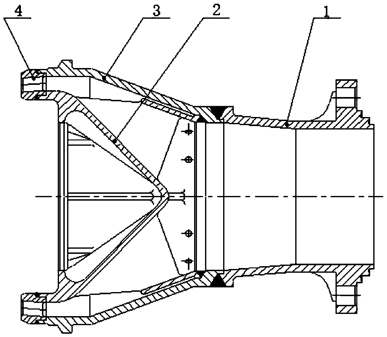
[0033] see Figure 1 to Figure 6 , a turbine inlet pipe structure for a rocket engine, the front section of the inlet pipe 1, the guide body 2, the inlet pipe shell 3 and the turbine stator 4.

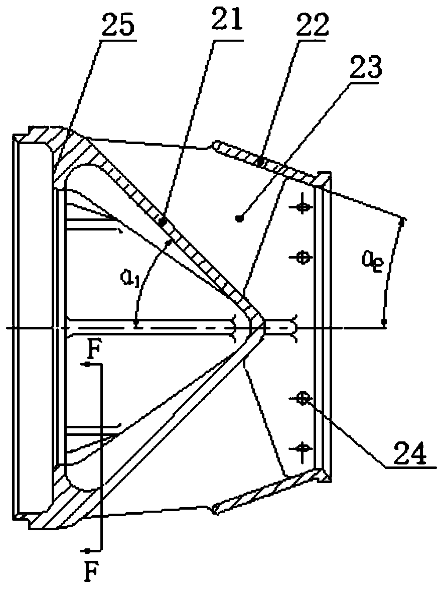
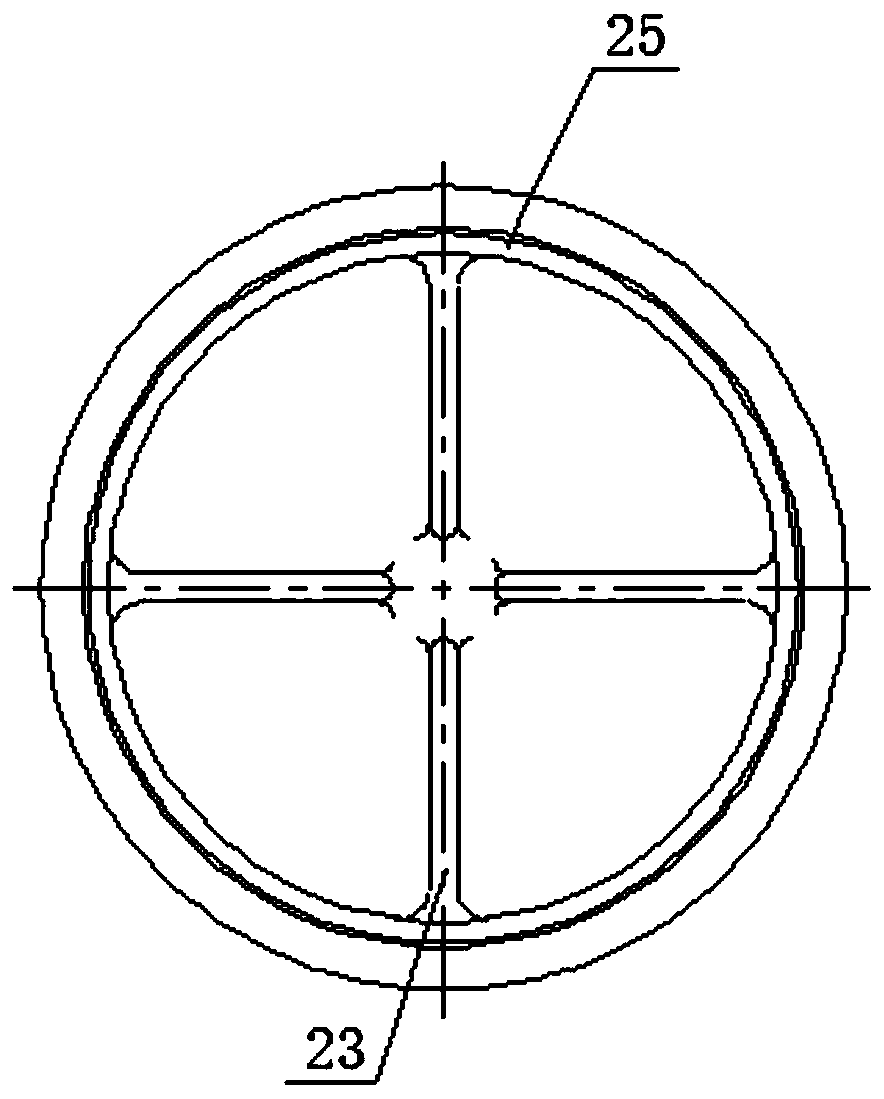
[0034] The guide body 2 is a key part in the turbine inlet pipe, mainly composed of four parts, namely the inner shell 21, the outer shell 22, the support plate 23 and the rib 26, and the whole is processed by casting, the inner shell 21 is a ho...


PUM


Abstract

The invention belongs to the field of liquid rocket engine turbine pumps, and particularly relates to a turbine inlet pipe structure for a rocket engine. The turbine inlet pipe structure aims to solvethe problem of the large axial dimensions of the engine turbine pump while guarantee the even air flow at an inlet of a turbine stator. The turbine inlet pipe structure comprises a flow guiding body,an inlet pipe shell and the turbine stator; the inlet pipe shell is of a rotary body structure and comprises an expansion section and a horizontal section connected with the large end of the expansion section; the flow guiding body comprises an inner shell and an outer shell; the inner shell is of a hollow conical structure, and the outer shell is of a hollow round-table-shaped structure; the outer wall and the inner shell are coaxially arranged, a channel with the open area being gradually decreased is formed between the outer wall of the inner shell and the inner wall of the outer shell, and the outer shell and the inner shell are connected together through a plurality of supporting plates arranged between the outer shell and the inner shell; and the flow guiding body is arranged in theinlet pipe shell, wherein the small end of the outer shell is fixedly connected with the small end of the expansion section of the inlet pipe shell, and the large end of the inner shell and the largeend of the expansion section of the inlet pipe shell are fixedly connected together through the turbine stator arranged between the large end of the inner shell and the large end of the expansion section of the inlet pipe shell.

Description

technical field [0001] The invention belongs to the field of liquid rocket engine turbine pumps, and in particular relates to a turbine inlet pipe structure for rocket engines. Background technique [0002] Rocket engine turbine inlet gas is obtained by burning oxidant and fuel in the generator, and has the characteristics of high temperature and high pressure. The generator generally uses multiple nozzles to organize combustion, and there is a large difference in the airflow temperature of the outlet section. The airflow temperature in the core area facing the nozzle is high, and the temperature between the two nozzles is low. Sometimes the airflow temperature in the core area of ​​the nozzle is very high, and the gas may have exceeded the bearing range of the turbine stator if the gas is not fully mixed, resulting in ablation of the turbine stator. Additionally, non-uniform turbine inlet gas can lead to poor turbine performance. [0003] To solve this problem, a common m...

Claims


Application Information

Patent Timeline
Patent Type & Authority Patents(China)
IPC IPC(8): F02C7/04
Inventor 毛凯王晓锋于晴李惠敏宣统李向阳李春乐
Owner XIAN AEROSPACE PROPULSION INST
Learn More