
Control Mechanism of Variable Intake Manifold Sectional Area of ​​Automobile Engine

A technology for automobile engines and intake manifolds, applied in combustion engines, machines/engines, internal combustion piston engines, etc., can solve problems such as weakening the power output of automobile engines, affecting the overall layout of the engine compartment, and hindering air intake into cylinders, etc., to achieve change Smooth, low cost and long service life effect

Inactive Publication Date: 2017-04-19
罗建民
View PDF5 Cites 0 Cited by
  • Summary
  • Abstract
  • Description
  • Claims
  • Application Information

AI Technical Summary

Problems solved by technology

[0004] For the technology of variable intake manifold length of automobile engine: if the length of variable intake manifold is insufficient, it will not play much role, especially for small displacement automobile engines; if the length of variable intake manifold is The length is sufficient, and the volume is easy to be too large and affect the overall layout of the engine compartment, which brings constraints and limitations to the technology of variable intake manifold length for automobile engines
For the technology of variable intake manifold cross-sectional area of ​​automobile engine, judging from the current automobile market, there are not many manufacturers with variable intake manifold cross-sectional area technology of automobile engine, and their variable intake manifold The cross-sectional area technology generally adopts the rotary vane type, the control system is relatively complicated, and the processing cost is high
In addition, the central rotating shaft of the rotary vane also hinders the air from being sucked into the cylinder, which weakens the maximum power output of the car engine.

Method used


Image

  • Control Mechanism of Variable Intake Manifold Sectional Area of ​​Automobile Engine
  • Control Mechanism of Variable Intake Manifold Sectional Area of ​​Automobile Engine
  • Control Mechanism of Variable Intake Manifold Sectional Area of ​​Automobile Engine

Examples


Embodiment Construction

[0023] The content of the present invention will be further described below in conjunction with the accompanying drawings and embodiments, but the present invention is not limited thereto.

[0024] The invention is designed according to the relay principle and the screw rod principle. The damper of the variable intake manifold of the engine adopts a movable sleeve structure, and the inner movable sleeve is used to rotate back and forth in the outer fixed sleeve to realize the cut-off of the intake manifold of the automobile engine. The area is variable, and various types of automobile engines are applicable. This example takes a four-cylinder gasoline engine as an example.

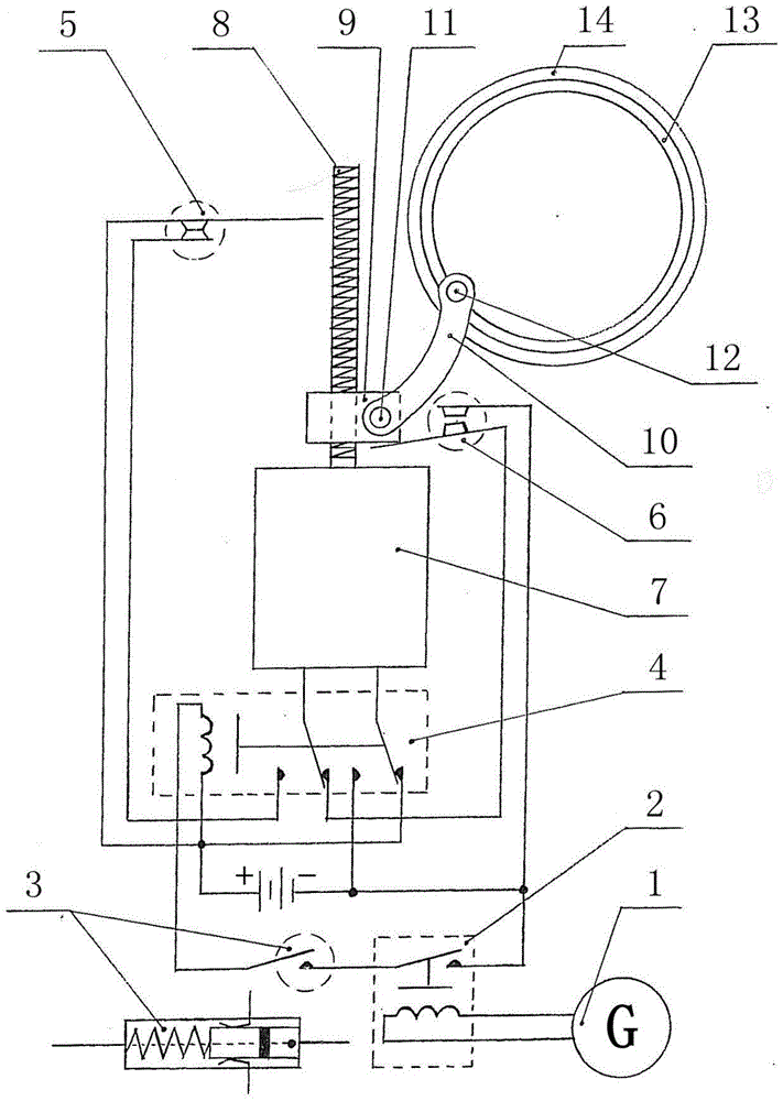
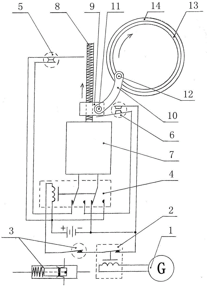
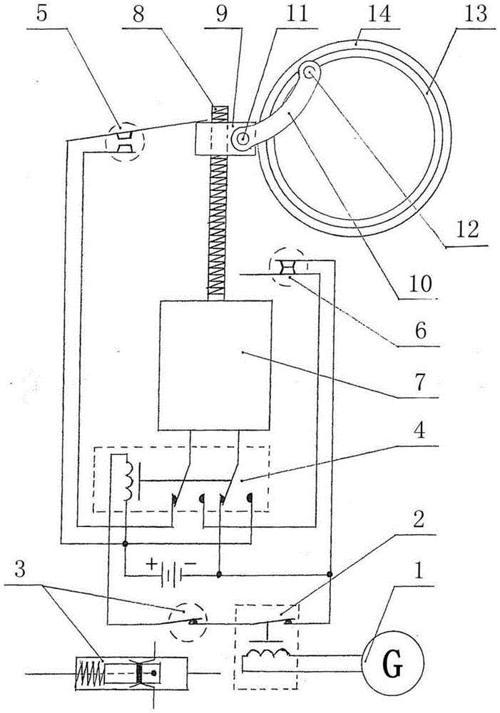
[0025] A variable intake manifold cross-sectional area control mechanism for an automobile engine, mainly composed of a simple generator 1, a single-contact relay 2, an accelerator signal switch 3, a four-contact relay 4, an upper stop normally closed contact switch 5, a lower Stop position normally closed...


PUM


Abstract

The invention discloses a variable-intake manifold section area control mechanism for an automobile engine. The variable-intake manifold section area control mechanism for the automobile engine is composed of an information circuit component, a drive component and an intake manifold component; the information circuit component comprises a direct current power supply, a simple generator 1, a single-contact relay 2, an accelerator signal switch 3, a four-contact relay 4, an upper stop normally-closed contact switch 5 and a lower stop normally-closed contact switch 6; the drive component comprises a direct current motor 7, a screw rod 8, a nut and a connecting bar 10; the intake manifold component comprises an inner movable sleeve 13, an outer fixed sleeve 14 and an intake manifold 15. When the information conforms to set conditions, the direct current motor forwardly or reversely drives the inner movable sleeve to reciprocally rotate in the outer fixed sleeve so as to realize the intake manifold section area change of the automobile engine. The intake condition of the engine is improved, by means of the air inflation effect of air current, the low-speed torque of the automobile engine can be improved, and the oil consumption and emission are lowered.

Description

technical field [0001] The invention relates to the technical field of automobile engines, in particular to an automobile engine variable intake manifold sectional area control mechanism. Background technique [0002] The intake manifold of the automobile engine is located between the throttle valve and the engine cylinder, its inlet is connected with the throttle valve, and its outlet is connected with the engine cylinder. The intake manifold corresponds to the number of engine cylinders, and each cylinder has an intake manifold, such as a four-cylinder engine has four intake manifolds, and a six-cylinder engine has six intake manifolds. into each cylinder separately. The design of the intake manifold is very knowledgeable. In order to make the combustion conditions of each cylinder of the engine the same, the length and curvature of the intake manifold of each cylinder should be the same as possible. [0003] The variable intake manifold of automobile engine is to improv...

Claims


Application Information

Patent Timeline
Patent Type & Authority Patents(China)
IPC IPC(8): F02B27/02
CPCY02T10/12
Inventor 罗建民
Owner 罗建民
Learn More