
Use and installation method of kitchen range energy gathering and heat insulation ring

An installation method and heat insulation ring technology, applied in the direction of furnace/stove furnace top, etc., can solve problems such as the inability to adjust the diameter of the energy-saving ring, excessive carbon monoxide emissions, and insufficient combustion of gas, so as to facilitate large-scale popularization and reduce carbon monoxide Emissions and energy-saving effects are remarkable

Inactive Publication Date: 2015-12-16
李孝龙
View PDF0 Cites 0 Cited by
  • Summary
  • Abstract
  • Description
  • Claims
  • Application Information

AI Technical Summary

Problems solved by technology

[0002] For the embedded gas stoves currently used in households, when the burner is burning, the air is supplemented by the surrounding and above the burner, and it is easy to form a near-vacuum state at the center of the burner, causing the flame at the center of the burner to lack oxygen Complete combustion leads to low combustion efficiency. The high-temperature area of ​​the flame generated is located around the pot body and not in the center of the pot body. A large amount of heat energy diffuses around the pot body and the burner, and the work efficiency is less than 60% (national standard GB16410 " Household Gas Cookers" stipulates that the thermal efficiency of embedded cookers is greater than 50%), a serious waste of energy, excessive carbon monoxide emissions, harmful to the environment and health
[0003] In order to reduce the heat loss around the burner and the pot body, windproof energy-saving rings are often installed around the burner in households. However, most windproof energy-saving rings simply surround the burner and prevent the air from entering, which in turn causes gas combustion. Inadequate (especially when used on built-in cooktops), more wasteful energy, excessive carbon monoxide emissions
In addition, the caliber of the current energy-saving ring cannot be adjusted, and the high-temperature heat energy generated by the burner of the pot with a small bottom diameter gathers around the pot body, which easily causes damage to the pot body and handle, and makes it impossible to operate.

Method used


Image

  • Use and installation method of kitchen range energy gathering and heat insulation ring
  • Use and installation method of kitchen range energy gathering and heat insulation ring
  • Use and installation method of kitchen range energy gathering and heat insulation ring

Examples


Embodiment 1

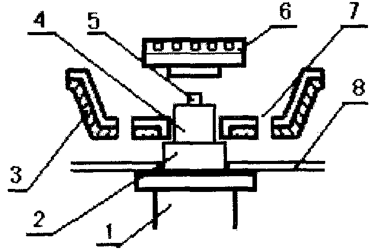
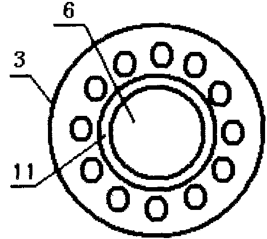
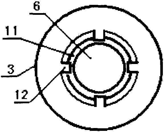
[0096] see figure 1 and Picture 1-1 , as shown in the figure, the energy-gathering insulation ring 3 passes through its lower central hole 10 (see image 3 ) is installed on the burner step 2 above the burner 1, the center hole 10 of the lower part of the energy-gathering heat insulation ring 3 is located outside the gas outlet 4 of the burner outer ring at the same time, and the burner 6 is installed on the burner outer ring gas outlet 4 and the center On the air outlet 5, since the energy-gathering heat-insulation ring 3 is installed on the burner step 2, the distance between the energy-gathering heat-insulation ring and the water tray 8 or the stove top is increased, and the air inlet hole at the bottom of the energy-gathering heat-insulation ring is increased. 7 air intake, so as to ensure the oxygen supply required for the combustion of the burner above the burner, while gathering energy and heat insulation, it can ensure the full combustion of the gas, improve the comb...

Embodiment 2

[0105] see Figure 4, as shown in the figure, an annular step is provided on the outer side of the burner base 11 above the burner head 1, and the energy-gathering heat-insulating ring 3 is installed on the annular step through its central hole, increasing the distance between the energy-gathering heat-insulating ring and the lower water pan or cooker table top. Therefore, by increasing the oxygen supply to the burner of the burner at the bottom of the energy-gathering heat insulation ring, it can ensure the full combustion of the gas and improve the combustion efficiency while the energy-gathering and heat-insulating ring, and can be easily disassembled and assembled. clean. In application, the outer circumference of the burner base 11 can be inclined ( Pic 4-1 shown in ) or a circular arc surface ( Figure 4-2 shown in), the energy-gathering heat insulation ring is installed on the inclined surface or circular arc surface on the outside of the base through its central hol...

Embodiment 3

[0110] see Figure 5 , as shown in the figure, the mounting ring 14 is fixed around the base of the burner 6 through the head screw 13, and the energy-gathering heat insulation ring 3 is arranged above the mounting ring, so that the heat energy generated by the burner is gathered above the burner, preventing thermal energy Spread around the burner to reduce heat loss.

[0111] In application, steps or outward flanges can be provided above the mounting ring.

[0112] In applications, the mounting ring spring clip 15 can be used inside the mounting ring (see Image 6 ) Instead of the head screw 13, the installation ring is clamped around the burner base through the installation ring spring clip. In application, the installation ring 14 can also be clamped around the burner base through the lower spring clip 16 (see Figure 7 ).

[0113] In application, the mounting ring can also be installed directly on the annular step around the base of the burner, or on the inclined surfac...


PUM


Abstract

The invention relates to a use and installation method of a kitchen range energy gathering and heat insulation ring. The ring comprises heat insulation slices and an installation ring and is characterized in that the heat insulation slices are inserted into insert keys, slots, bayonets, necks, sockets, rotation shafts or rotation shaft slots around the installation ring by insert keys, slots, bayonets, necks, sockets, rotation shafts or rotation shaft slots at the bottoms of the heat insulation slices, the energy gathering and heat insulation ring is formed around a burner, the installation ring is located at an annular step located at the outer side of a burner base, a peripheral oblique face or a circular surface at the outer side of the base, or is combined with the burner base. The size of the energy gathering and heat insulation ring can be adjusted and is suitable for pots with different bottom diameters so that the problem that the periphery and a pot handle of a pot with a small bottom diameter are easily damaged by a high temperature produced by the energy gathering and heat insulation ring is solved. The kitchen range energy gathering and heat insulation ring improves air inlet conditions, improves combustion efficiency, reduces carbon monoxide discharge and has high efficiency and environmental friendliness. The kitchen range energy gathering and heat insulation ring does not change a kitchen range structure, can be installed on the existing kitchen range, is simple, fast and convenient, is convenient for large scale popularization and has use safety.

Description

[0001] The invention relates to an energy-gathering and heat-insulating device for a gas cooker, in particular to an application and an installation method of an energy-gathering heat-insulating ring on a cooker. Background technique [0002] At present, in the embedded gas stoves used in the home, when the burner is burning, the air is supplemented by the surrounding and above the burner, and it is easy to form a near-vacuum state at the center of the burner, resulting in the flame lack of oxygen in the center of the burner. Complete combustion, resulting in low combustion efficiency, the high temperature area of ​​the generated flame is located around the pot body and not in the center area of ​​the pot body, a large amount of heat energy is diffused around the pot body and the burner, and the working efficiency is less than 60% (National Standard GB16410 " "Household Gas Cookers" stipulates that the thermal efficiency of embedded cookers is greater than 50%), which is a seri...

Claims


Application Information

Patent Timeline
IPC IPC(8): F24C15/10
Inventor 李孝龙
Owner 李孝龙
Learn More